






Climb milling vs conventional milling describes the direction of feed relative to cutter motion at the engaged edge. For peripheral milling, the two directions produce different chip-entry sequences. Select the direction only after checking the machine, fixture, stock and cutting tool. A CNC label alone does not settle the choice. [1]
This guide explains when to use climb milling through a direction sketch and a setup-review method. It supplies no cutting-speed recommendation, tool-life percentage or MW+ production result. The illustrated passes are hypothetical.
Climb milling vs conventional milling: identify the engaged side
Begin a climb milling vs conventional milling review with a plan view perpendicular to the cutter axis. Mark the cutter rotation, the stock boundary and the direction the workpiece travels relative to a fixed cutter. Then mark the tangent motion of the tooth at the engaged side. Keep those references consistent throughout the sketch.
In the hypothetical drawing below, the cutter rotates counterclockwise when viewed from above. At its lowest point on the page, the tooth moves right. The workpiece lies below the cutter. Feeding that workpiece right gives the climb case; feeding it left gives the conventional case. These statements apply to the illustrated contact, not to every edge of a pocket.
For a climb milling vs conventional milling comparison on the opposite side of a cutter, redraw the contact before classifying the pass. The tangent motion on the opposite side points the other way. Likewise, a screen arrow showing tool travel over a stationary workpiece uses a different reference from an arrow showing workpiece travel past a stationary cutter. State which one you mean. [1]
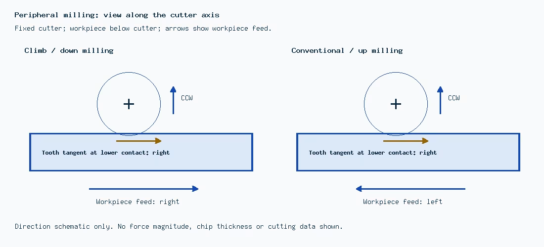
For climb milling vs conventional milling, use the sketch as a communication check before discussing finish or production time. Ask the programmer and operator to identify the same engaged edge independently. If they point to different stock boundaries, resolve that discrepancy first. Otherwise, two people can agree to “climb” while picturing different passes.
Down milling and the chip-entry sequence
Down milling is another name for climb milling. In the peripheral case described by Sandvik Coromant’s direction guidance, the chip begins thicker and becomes thinner toward exit. Conventional cutting starts at zero chip thickness and increases toward exit. The distinction concerns chip formation, rather than a guaranteed surface result. [1]
When comparing climb milling vs conventional milling, keep the geometry and the actual tool application with that statement. Down milling guidance for an open peripheral cut cannot describe every engagement in a full-width slot. Identify the material-removal region and ask the toolmaker which guidance applies to that operation.
Up milling and the conditions that can justify it
Up milling is the conventional direction. Sandvik identifies variable working allowance and ceramic inserts in heat-resistant alloys among the conditions that can favor it. Preserve those conditions when discussing climb milling vs conventional milling; do not turn a conditional preference into a universal CNC rule. [1]
For a proposed up milling pass, ask what problem the direction addresses and which document supports it. Then check the actual tool grade, material and stock condition against that explanation. A review names the condition and the evidence needed to accept it, rather than treating an exception as an automatic instruction.
| Review question | Climb case | Conventional case |
|---|---|---|
| What is the chip sequence? | Thicker entry toward thinner exit. | Zero-thickness entry toward thicker exit. |
| What fixture demand needs attention? | Resist pulling into the cut. | Resist lifting from the table. |
| What machine condition matters? | Control table-feed play and unintended pull-in. | Review the same machine condition and the reason for selecting this direction. |
| Does the name predict the finished surface? | Agree the tool, engagement, drawing requirement and acceptance evidence separately. | |
Check the machine, workholding and stock before selection
A climb milling vs conventional milling review should include milling backlash: lost motion or play relevant to the table-feed system. Sandvik warns that pull-in can unintentionally increase feed if the machine cannot control that play. Record the applicable machine condition and the operator’s approved setup procedure. Do not infer that a machine is suitable from its age or controller name alone. [1]
For workholding, sketch the contacts that locate the part and those that restrain it. Then ask where the cutting action can pull or lift the workpiece in the planned pass. Mark the restraint in that direction. Keep a diagram of the actual fixture beside the toolpath so a general statement about clamping does not substitute for a review of this setup.
In a climb milling vs conventional milling discussion, the direction arrow belongs to the actual pass. A clamp on one side of a plate does not describe support at another edge. Check the approach and exit as well as the middle of the cut. If the pass changes the available restraint, ask the process owner to review that stage explicitly.
Next, describe the incoming stock. Record whether the allowance is uniform and which surfaces establish the starting geometry. If it varies, show where the largest and smallest engagement occur. Request the applicable cutting-tool guidance before selecting a direction on that basis. Keep assumed stock separate from inspected incoming material.
Also identify the surface being generated. Sandvik’s shoulder-milling guide distinguishes operations that generate a shoulder and face together from peripheral edging. Use the actual required surfaces to define the operation under review. [2]
| Observed or proposed condition | Review action | Record before approval |
|---|---|---|
| Open peripheral pass on uniform stock | Identify the contact and compare the proposed direction with applicable tool guidance. | Rotation/feed sketch, tool identity, stock limits and setup approval. |
| Table-feed play is unresolved | Have the machine/process owner assess pull-in control before accepting a climb pass. | Machine condition and approved operating method. |
| Working allowance varies substantially | Review entry conditions with the actual tool and material. | Stock envelope and manufacturer application guidance. |
| Ceramic inserts in a heat-resistant alloy | Retain the toolmaker’s material-specific direction advice. | Insert grade, alloy and relevant application document. |
| A wall or fixture changes between passes | Reassess local support and acceptance for the changed geometry. | Pass-specific sketch and inspection plan. |
Document the choice and inspect the required surfaces
To decide when to use climb milling, assemble the rotation/feed sketch, tool identity, stock condition and fixture review before approving the route. Then state the reason for the selected direction. This makes a climb milling vs conventional milling decision traceable when a tool, material batch or fixture changes.
For the hypothetical paired passes, assume the same open edge and the same cutter orientation. Change only the workpiece-feed arrow in the sketch. This isolates the meaning of the direction names. It does not establish that both passes are acceptable on a real machine or that either produces a specified roughness.
After that conceptual check, add the actual process inputs. Request the toolmaker’s cutting data for the chosen tool and material, and have the process owner confirm the engagement. Keep these inputs with the approved route. The climb milling vs conventional milling label cannot supply spindle speed, feed, tool condition or machining allowance.
For acceptance, identify the drawing-controlled surfaces and the evidence that will be reported. Ask which dimensions are checked after roughing, which after finishing, and how the inspected locations relate to the functional surfaces. If the review changes the route, identify which inspection assumptions must be revisited before release.
Keep the climb milling vs conventional milling review focused on cutting direction. Use the thin-wall machining guide for the part-support and deflection question. Describe the relevant precision component interfaces before requesting a CNC manufacturing review. Share the controlled drawing and process questions with MetalWorksPlus.
Key takeaways
- Mark rotation, contact and the reference used for the feed arrow.
- Treat climb milling vs conventional milling as a conditional process decision.
- Record machine, fixture, stock and tool evidence before approving the pass.
Frequently asked questions
Is climb milling the same as down milling?
The names refer to the same direction. For a climb milling vs conventional milling comparison, use a sketch that states the engaged side and feed reference. The peripheral chip sequence then helps explain the difference. [1]
Is conventional milling ever preferable?
It can be, under the conditions in the applicable toolmaker guidance. Check variable stock, machine constraints and material/tool exceptions instead of applying one direction to every operation. [1]
Why does milling backlash matter?
Uncontrolled table-feed play can permit unintended pull-in during a climb pass. Have the machine and process owner assess the actual setup before approving that route. [1]
Does climb milling always give a better finish?
The direction name cannot establish an acceptance result. Complete the climb milling vs conventional milling review with the actual tool, setup and drawing requirements, then verify the produced surfaces using the agreed inspection plan.