








Thin wall machining needs a coordinated review of wall geometry, support, cutting sequence and final inspection condition. Wall thickness alone is not a reliable measure of machining difficulty. Sandvik’s thin-wall guidance considers height and thickness together and calls for stability of both the cutter and workpiece. [1] Define the feature and its acceptance state before choosing a manufacturing route.
This guide explains the engineering decisions behind that review. It separates a simple static-deflection calculation from vibration assessment and from movement observed after unclamping. All numerical examples are hypothetical teaching models, not measured MW+ performance, cutting-force data, material certification or approved wall dimensions. No customer project or production capability is claimed.
Contents
Thin wall machining starts with the supported geometry
Identify the wall on a sectioned drawing. Record its thickness, unsupported height, length, base connection and nearby features. Mark whether it is a standing rib, a pocket wall, a thin floor or another geometry. Describe the section at the operation being reviewed rather than relying only on the final CAD shape.
Sandvik describes different approaches for thin standing walls and thin bases, with machining strategy depending on wall dimensions and available support. [1] A proposed method for one feature should therefore be reviewed against the actual component instead of copied to every thin section in the assembly.
What a minimum wall thickness for CNC guideline omits
Use a supplier guideline as a screening prompt, then ask which material, geometry, setup and acceptance conditions it assumes. Protolabs identifies tall, thin walls as a design concern in its machining guide. [4] That does not establish a universal minimum for MW+ or prove that a wall just above another supplier’s threshold is acceptable.
For the drawing review, distinguish a functionally required thin region from material that can remain thicker. Ask the design owner whether a shorter unsupported span, local support feature or modified wall profile is permissible. Obtain approval for any change; do not quietly thicken a seal interface, optical clearance or other controlled feature.
Also identify tool access. Record the deepest controlled surface and the clearance available for the complete tool assembly. The proposed process should address both the workpiece and the tool system. A shorter reach may be worth discussing, but the axis count or toolpath label does not by itself demonstrate dimensional capability.
Worked example: wall thickness and static bending
To isolate one geometric effect, model a narrow wall strip as an ideal, straight, rectangular cantilever. It is perfectly fixed at its base and loaded sideways at its free end. The bending-only tip-deflection relation is δ = FL³/(3EI), where F is the load, L the unsupported length, E the elastic modulus and I the section’s second moment of area. Ansys presents this relation and explains why omitted shear deformation can matter for other beam geometries. [3]
For this model, define b as the strip width and t as its thickness in the bending direction. Integrating y² over a rectangular section gives I = b∫y²dy from −t/2 to +t/2 = bt³/12. Substitution gives δ = 4FL³/(Ebt³). The thickness is therefore cubed in the denominator for this specifically defined model.
Assume F = 1 N, L = 20 mm, b = 10 mm and E = 70,000 N/mm². E is an assumed constant, not a certified property of any alloy or temper. The 1 N load is invented, not a cutting-force estimate. Compare four hypothetical thicknesses while holding those other inputs fixed.
| Assumed thickness t, mm | Calculated I = bt³/12, mm⁴ | Calculated bending-only tip deflection δ, mm |
|---|---|---|
| 0.80 | 0.426667 | 0.089286 |
| 1.00 | 0.833333 | 0.045714 |
| 1.20 | 1.440000 | 0.026455 |
| 1.50 | 2.812500 | 0.013545 |
Check the 1.00 mm row: I = 10 × 1³/12 = 0.833333 mm⁴. Then δ = 1 × 20³/(3 × 70,000 × 0.833333) ≈ 0.045714 mm. Dimensional consistency follows because E in N/mm² multiplied by I in mm⁴ gives N·mm²; FL³ divided by that quantity gives millimetres.
At fixed F, E, b and L, increasing t from 1.00 to 1.50 mm reduces the calculated deflection to 1/1.5³, approximately 29.63% of the original value. At fixed thickness, reducing L from 20 to 15 mm would multiply deflection by (15/20)³ = 0.421875. These are model sensitivities, not promised improvements for an actual machining operation.
Several limits are deliberate. The model assumes small-deflection linear elasticity, a perfect support, a slender beam and a constant end load. It omits plate behavior, changing contact location, dynamic cutting forces, thermal effects, residual stress and fixture compliance. Use it to understand the influence of thickness and unsupported length, then select an applicable analysis for the real geometry.
A low static-deflection estimate does not establish a chatter-free process. Nor does this calculation determine a finished-part tolerance. Ask the responsible engineer how the load, support and deformation model will be verified before using a calculated displacement in a manufacturing decision.
Plan thin wall milling as a sequence of supported states
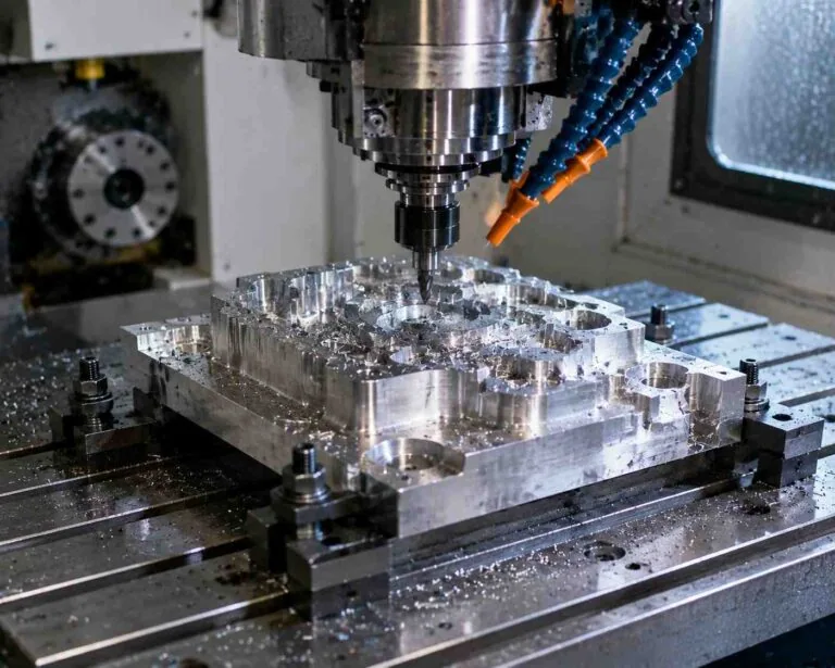
Sandvik’s thin-wall section describes approaches that alternate sides or retain supporting material while approaching the final wall in stages. [1] The relevant principle is to review the material still supporting the cut at each operation, rather than assume the final wall shape represents every intermediate condition.
Our recommended process review uses a small set of stage views. For each, identify the surfaces already finished, remaining stock, tool approach, fixture contacts and next material to remove. Ask the supplier to explain where the proposed sequence relies on temporary support and how that support will be removed without leaving an unverified final feature.
Separate a proposed finishing allowance from the required final wall thickness. Define which dimension is a process target and which is a released acceptance requirement. If the supplier proposes changing the allowance after a trial, review how that change affects the remaining operations and inspection, rather than treating it as unrelated to the process plan.
Do not turn the sequence discussion into a universal heat-treatment prescription. Protolabs notes that internal material stress or clamping can be associated with warpage after release. [4] Ask the material and design authorities what stock condition and any approved stabilization steps apply. This guide provides no thermal cycle, stress-relief temperature or claim that a pause between passes removes residual stress.
Review vibration through the complete machining system
Sandvik identifies the cutting tool, holder, machine, workpiece and fixture as potential contributors to milling vibration. Its guidance also considers cutting-force direction, support and cutting conditions. [2] Inspect the proposed system as a whole rather than assign every surface mark to a thin wall or every error to the machine.
For the engineering enquiry, request the actual tool assembly, overhang, workholding arrangement and operation sequence. Ask which direction is poorly supported and how the proposed toolpath addresses it. Keep any toolmaker cutting-data recommendation tied to its applicable tool, material and engagement conditions.
Reducing feed or spindle speed is not a universal remedy. Sandvik discusses both rubbing when chip thickness becomes too low and changes in stability with spindle speed. [2] The useful next step is a documented process review and controlled trial, not an unsupported instruction that every thin-wall operation should run more slowly.
As a trial-plan recommendation, keep the starting condition and measured outcomes identifiable. Record the part revision, setup, tool condition and parameters actually changed. Evaluate the drawing characteristics and relevant surface evidence after each approved change. Do not claim a cause from an uncontrolled comparison in which several variables changed together.
This article does not calculate stability lobes, select a toolmaker’s cutting data or predict a chatter threshold. Those tasks need their own applicable inputs and validation. Keep a static bending calculation, a dynamic process assessment and a finished-part inspection result as separate pieces of evidence.
Inspect the part in its specified condition
Define the condition in which each feature is accepted: its required supports, any restraint, orientation, finished treatment stage and relevant environmental controls. Do not assume that a reading taken while held in a machining fixture represents an unrestrained component. Movement after release is one reason Protolabs highlights thin-wall geometry and clamping in its guide. [4]
The following arithmetic example illustrates why the state must accompany the number. Assume a drawing thickness of 2.000 ±0.030 mm and, solely for the example, an acceptance condition with no applied fixture restraint. Invent two displayed readings at the same feature: 2.010 mm while restrained and 2.045 mm after release. These are hypothetical observations, not measurements of an MW+ part.
| Assumed observation state | Hypothetical displayed reading, mm | Difference from 2.000 mm nominal | Arithmetic comparison with 1.970–2.030 mm interval |
|---|---|---|---|
| Restrained in a fixture | 2.010 | +0.010 mm | Inside the numerical interval; not the assumed acceptance state |
| Released, without applied fixture restraint | 2.045 | +0.045 mm | 0.015 mm above the upper interval limit |
The difference between the displayed readings is 2.045 − 2.010 = 0.035 mm. Reporting only the first number would omit the example’s specified state. Conversely, the difference does not establish why the readings changed: a real investigation must examine support, contact, location, alignment, temperature and the measurement system.
NPL’s CMM measurement-strategy description covers sampling, loading and alignment, temperature, surface finish and geometry in relation to the result. [5] Agree the measurement plan against the actual drawing. A single local thickness reading should not silently become a complete evaluation of wall profile, flatness or position.
For a compliant region, ask the inspector to explain how the method interacts with the part and how its coverage is demonstrated. Record any inaccessible or unverified area. If a noncontact method is proposed, assess its suitability for the characteristic rather than assuming that absence of probe contact removes every measurement uncertainty.
Retain raw observations separately from evaluated characteristics and acceptance decisions. Identify drawing revision, feature, location, support state, method and any approved decision rule. For broader drawing terminology, the existing GD&T symbols guide explains how to read geometric controls without assigning a new tolerance to this component.
Design and manufacturing release checklist
Before quotation or a process trial, close these related questions:
- Geometry: Are thickness, unsupported height, base support and controlled length defined?
- Function: Which thin regions are essential, and which changes can the designer approve?
- Sequence: What supports the wall at each machining stage, including removal of temporary material?
- System: Have the cutter, holder, machine and fixture been reviewed with the workpiece?
- Material: Are stock condition and any treatment steps approved for the actual design?
- Inspection: Are the acceptance state, coverage and measurement definitions explicit?
- Evidence: Are trial observations, evaluated results and production controls documented without transferring unsupported performance claims?
Discuss the controlled wall within MW+’s precision machined component range. Use the CNC machining review to resolve sequence and inspection questions. Where tool access is a specific issue, the multi-axis service overview provides commercial context; confirm the actual setup rather than infer a thin-wall capability from axis count. Send MetalWorksPlus the model, released drawing, material condition and inspection requirements together.
Frequently asked questions
What is the minimum wall thickness CNC machining can achieve?
This guide provides no universal value. Review material, supported geometry, tool access, manufacturing sequence and acceptance conditions. Sandvik’s guidance explicitly considers wall height and thickness together. [1] Confirm a proposed value against the actual component and evidence required.
Does a thicker wall always eliminate machining deflection?
No such guarantee follows from the example. Increasing thickness reduces calculated bending for the fixed ideal model, but actual loads, support, geometry and process behavior remain unverified. Use the calculation as a sensitivity explanation rather than a production result.
Should thin wall milling always use a lower feed?
Do not use that as a blanket rule. Sandvik discusses cutting conditions and warns that insufficient chip thickness can cause rubbing and vibration. [2] Follow applicable toolmaker guidance and a reviewed process for the actual system.
Does the cantilever calculation predict chatter or residual-stress distortion?
No. It is a static, linear-elastic bending calculation under an assumed end load and perfect support. Its stated model does not include dynamic cutting forces, plate behavior, residual stress or fixture compliance.
Can a clamped reading replace a free-state inspection?
Use the inspection condition required by the released drawing and approved quality plan. In the hypothetical example, the restrained reading is explicitly not taken in the assumed acceptance state. Record the state with the result and resolve any mismatch before making a release decision.
Technical references
- Sandvik Coromant: Shoulder Milling: Thin Deflecting Walls. Wall height/thickness, cutter/wall stability and staged or alternating-side strategies. Vendor ratio bands and finishing allowances not adopted as universal rules.
- Sandvik Coromant: How to Reduce Vibration in Milling. Tool/holder/machine/workpiece/fixture system, force direction, support and cutting conditions; no universal speed or feed rule.
- Ansys Innovation Space: Point Loading of a Cantilever Beam: Pre-Analysis. Bending-only tip deflection PL³/(3EI); distinction from shear contribution and model assumptions. No example material/experimental data transferred.
- Protolabs: Definitive Guide to CNC Machining. Tall/thin-wall design concern and movement after release associated with internal stress or clamping. Supplier limits and general/legacy GD&T advice not adopted.
- National Physical Laboratory: CMM Measurement Strategies GPG41. Sampling, loading/alignment, temperature, geometry and drawing-linked measurement planning. Public guide description checked; no universal sample count specified.
Sources reviewed on 27 October 2026. Review checklists are engineering recommendations. Numerical inputs and inspection readings are assumed illustrations; none establishes MW+ equipment, measured results, customer outcomes or a qualified minimum wall thickness.