







For a fillet vs chamfer decision on a machined part, choose the external edge that serves the interface. A convex radius rounds the change between faces. A chamfer creates a flat bevel. Use the rounded profile when the edge needs a smooth transition for handling, or a defined bevel when it must guide a mating part. Check that the selected edge leaves enough locating or seating surface. [1, 2]
This guide covers the outside edges of machined components and the nearby shoulders they may affect. It explains when to use a fillet or chamfer through an example in which the usable flat, rather than the overall part width, decides which dimensions should go on the drawing.
Fillet vs chamfer: compare the two profiles in section
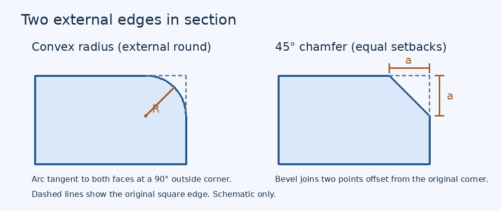
An external corner radius at a square outside corner is a convex arc that can meet both original faces tangentially. Drawings and conversations may call it an external round or a convex fillet. A bevel replaces the corner with a straight line in the section perpendicular to the edge. Protolabs’ manufacturing guide shows both profile types. [1]
For a fillet vs chamfer comparison, draw the original intersection as a reference, even though that sharp vertex will be removed. If a 90° corner is rounded by a tangent circular arc, the tangent point is one radius from the original vertex on each face. In a 45° chamfer at the same corner, the setbacks on the two faces are equal. The pair may remove the same length of flat face with different remaining profiles.
| Profile | Geometry to define | Use it when | Evidence to agree |
|---|---|---|---|
| Convex round | Radius, adjacent faces, the required extent and any blend or termination condition. | The design needs a smooth transition on a handled or exposed edge. | Profile at agreed sections and the usable mating flat. |
| Chamfer | Setback on a named face and angle relative to a named face, or two setbacks that define the bevel. | A defined planar lead-in or a predictable envelope matters. | Size and angle or both setbacks, plus location, extent and available flat. |
External corner radius and bevels serve different functions
With a cover or handle, first trace the area a person grips, plus the corners they may touch during installation. A rounded profile can give a smoother transition between adjoining faces. However, identify any seam edge that also aligns with another part before extending the round all the way around. The two functions can call for different treatment on the same component. [1]
For a fillet vs chamfer drawing review, start with the feature the edge is meant to protect. If the objective is hand contact, define the boundary around the reachable edge. If the objective is lead-in, sketch the mating part at entry and identify which face it approaches. In addition, check what happens after entry, when the mating part must seat on an adjacent flat.
A fillet vs chamfer choice on an exposed convex edge does not establish a strength or fatigue improvement. For a loaded section transition, separately review the actual load path, profile, section remaining and the mating clearance. Apply any stress or life evaluation to that geometry. This guide does not generalize a supplier machining example into a strength rule. [1]

Protect the seating face and assembly clearance
Chamfer edge design at the cover and shaft interfaces
Start a chamfer edge design review by marking the direction of insertion and the final contact area. A bevel at a shaft end may guide a mating component into position. However, the end lead-in and a radius at a shaft shoulder are separate features. Compare the shoulder profile against the mating component’s approved relief before specifying the radius or bevel. Check both initial engagement and final seating.
In this hypothetical fillet vs chamfer example, assume a cover has a flat locating land bounded by two opposed 90° exposed edges. The pre-treatment distance between the theoretical intersections is 8.00 ± 0.10 mm. The mating component needs at least 7.00 mm of uninterrupted flat. Assume symmetrical nominal treatments, unaffected flats, two dimensioned edges and a two-dimensional section. No coating, form error or measurement uncertainty is included.
For this fillet vs chamfer calculation, subtract the maximum setback on both sides from the minimum width. For a 0.35 ± 0.05 mm tangent radius, each maximum setback is 0.40 mm. For a 0.50 ± 0.05 mm chamfer specified by its setback on the controlled face, each maximum setback is 0.55 mm. The 45° profile is assumed, but the setback on the locating face is what enters the land calculation.
| Feature and option | Check | Drawing and acceptance decision |
|---|---|---|
| Cover with a tangent radius at both edges | 7.90 − 0.40 − 0.40 = 7.10 mm minimum flat. | 0.10 mm margin in the simplified model. Inspect the profile where it meets the locating land. |
| Cover with a 45° chamfer at both edges | 7.90 − 0.55 − 0.55 = 6.80 mm minimum flat. | 0.20 mm below the assumed requirement. Reduce the setback or increase the available width, then check again. |
| Shaft shoulder against a mating ring | Compare the actual shoulder envelope with the approved ring relief. | Specify the functional shoulder and agreed profile. Verify the ring reaches the intended locating face. |
| Exposed grip edge with no mating face | Identify the reachable length and its terminations. | Agree how to check the transition at corners and where the treatment ends. |
In a fillet vs chamfer review, the usable land is a distance between the actual transitions where the flat ends. If the acceptance drawing dimensions only the outside envelope, ask the designer whether the land needs its own minimum. That gives the inspector a direct measurement even when the two alternative profiles are dimensioned differently.
These fillet vs chamfer cases compare chosen dimensions on the same part. If both profiles were limited to 0.40 mm setback on each side, both would leave 7.10 mm in this section. For the next fillet vs chamfer iteration, first keep the allowable footprint fixed, then judge whether each profile still delivers the desired handling or lead-in. A chamfer edge design can be retained if its smaller setback still serves the interface.
Make the drawing usable for machining and inspection
Whichever profile you choose in the fillet vs chamfer comparison, specify the exact edge, its bounding faces, its size limits and whether the feature is continuous. For a fillet vs chamfer callout, mark where a local requirement takes precedence over the general edge-break note. Also identify any protected datum target or contact land. If a coating affects the intended fit, state the condition in which the edge or land is accepted.
A useful fillet vs chamfer drawing has a close-up view if nearby edges look alike in the overall view. Mark the start and stop points using features already controlled on the drawing. Then carry those locations onto the inspection report so a reading from a convenient edge cannot stand in for one from the functional edge.
Before quoting the fillet vs chamfer alternatives, ask the machinist to confirm cutter and holder access at the first and last point on the edge. On a milled cover, check the vicinity of clamps and nearby walls. On a turned feature, ask the supplier how the chuck-side edge will be reached and whether it needs another setup. Sandvik Coromant’s chamfer milling guidance identifies setup, front or back access, bevel angle, depth and material as tool-selection inputs. [2]
Then define the inspection evidence. For a critical fillet vs chamfer decision, agree on the sections to measure and on the method appropriate to the controlled feature. For example, request a setback measurement and the angle relative to a specified face where both are functional. For an external corner radius, request a profile check over the portion the drawing requires. Verify the uninterrupted flat independently where the mating part uses it.
To decide when to use a fillet or chamfer on an existing drawing, bring the mating model, edge conditions and acceptance references to CNC machining drawing review. Identify which precision component interfaces depend on the edge. Share the controlled package with MetalWorksPlus so manufacturing can check access and the proposed inspection method.
Key takeaways
- Classify each edge by function before dimensioning its profile.
- For a fillet vs chamfer comparison, calculate the usable flat after the maximum setbacks.
- Specify which edges and datum areas the general edge note excludes.
Frequently asked questions
What is the difference between an external round and a chamfer?
In a fillet vs chamfer section, the convex round uses a curved profile such as a tangent circular arc. The chamfer is a flat bevel. Both remove the theoretical sharp corner. Compare the actual setbacks to see how much of the adjoining faces remains. [1]
Is a fillet always stronger than a chamfer?
An edge description alone cannot establish strength. Evaluate the actual load, section and transition geometry. The outside-edge example in this guide compares remaining flat width and contains no stress or fatigue calculation.
When should an external chamfer be controlled separately?
Give the edge its own requirements when its size or angle affects entry, seating, clearance or inspection. Identify which beveled edges are excluded from a general note and verify them on the correct faces.
Can a general edge-break note replace a radius callout?
Use a local radius callout where the profile and its limits affect function or acceptance. A general note can address other edges if the drawing defines its scope and the supplier and inspector can identify the exceptions.