







Clevis pin design starts by tracing the force from the centre member into both clevis ears. Calculate the average pin shear and projected bearing stress at each member. Then check bending, retention and geometry separately. A balanced double-shear calculation depends on the two ears sharing the load, as in the symmetric example below. [1, 2]
Illustrative application guide. This example explains how to check pin loads using assumed dimensions and a static force. The values are a teaching exercise. They establish neither a safe working load nor a MetalWorksPlus project result.
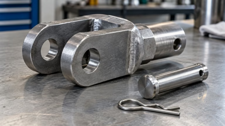
Clevis pin design: trace the load through the three members
In the example, a centre link sits between two clevis ears. A straight pin passes through all three holes. For symmetric static loading, assign half the applied transverse force to each outer ear and the full force to the centre link. The planes at the transitions between the centre and outer members are the two nominal shear planes. The Air Force Stress Analysis Manual, section 9.4, treats symmetry and pin bending explicitly. [1]
For a clevis pin design review, draw the load arrows on a section through the pin axis. Put the overall load on the centre member and a reaction on each ear. Then mark the bearing lands, clearances, head, washers and retention feature. Keep the pin diameter at each loaded section visible. This makes it easier to spot a shoulder, thread or cross-hole that intrudes into a section assumed to be solid.
In clevis joint design, first establish how the parts are assembled and which member rotates in service. If one ear has clearance that delays contact, or if the linkage applies a side load, review the resulting load distribution before assuming equal reactions. Symmetry in the drawing alone does not establish symmetry of contact. [1]
A clevis pin design calculation also needs a defined loading case. Record whether the force is static or cyclic, its direction, and the conditions under which it acts. A machine linkage with uncertain shock, misalignment or cyclic loading needs an analysis and validation plan based on the actual duty. In this worked example only the stated idealized static condition is analyzed.
Clevis pin shear strength starts with the loaded section
A practical clevis pin design check begins by labelling the diameter at the two interfaces. If the same pin has a smaller diameter near one interface, the nominal shank calculation cannot describe that location. Mark the minimum specified section on the sketch and let the designer decide which local geometry needs separate analysis.
To evaluate clevis pin shear strength, first determine the average shear stress demanded by the assumed load. Use A = πd²/4 for an intact circular section of diameter d. In the balanced model, each plane carries F/2, giving average shear stress τ = F/(2A). This arithmetic calculates demand. To evaluate capacity, the designer also needs a verified material and an applicable basis for allowable stress. [1]
Pin bearing stress at the centre member and ears
Calculate nominal pin bearing stress using the load on the member divided by the projected area d × t, where t is the effective bearing thickness. Use the full applied load at the centre link and half at each ear in this model. The calculation gives an average based on projected area. The actual contact pressure can vary across a member when the pin bends or the contact is uneven. [1]
Assume a 2,400 N force, a solid 10.00 mm pin, an 8.00 mm centre member, two 6.00 mm ears and a 0.50 mm gap on each side. These are nominal teaching inputs. In a released clevis pin design, evaluate the specified minimum loaded diameter, effective engagement and applicable limit dimensions. Use N and mm throughout. Therefore, the stress unit N/mm² equals MPa.
| Location | Assigned force (N) | Area (mm²) | Calculated average stress (MPa) |
|---|---|---|---|
| One pin shear plane | 1,200 | 78.54, circular section | 15.28 shear |
| Centre link bearing zone | 2,400 | 80.00, projected | 30.00 bearing |
| Each clevis ear bearing zone | 1,200 | 60.00, projected | 20.00 bearing |
The centre member has the higher calculated projected bearing stress in this clevis pin design example. That comparison alone cannot identify the governing member. Before that judgement, compare each demand with the applicable criteria for its own material, geometry and service condition. Likewise, review the remaining material beyond and beside each hole. The Air Force manual treats lug failure and pin failure as separate checks. [1]
Check what changes when the clearance gap grows
In a clevis pin design, the two ear reactions act some distance from the centre member load. Under the symmetric model with uniform load through each member thickness, the Air Force manual gives M = (F/2)(te/2 + tc/4 + g). Here te is one ear thickness, tc is centre thickness, and g is the equal gap on each side. [1]
For a solid circular section in elastic bending, use σ = 32M/(πd³). A published NASA contractor report on a clevis test fixture illustrates the value of checking bending alongside shear for a specified assembly. Its fixture geometry and loads differ from this example. [2]
| Gap per side (mm) | Moment arm term (mm) | Calculated moment (N·mm) | Calculated elastic bending stress (MPa) |
|---|---|---|---|
| 0.50 | 5.50 | 6,600 | 67.23 |
| 1.50 | 6.50 | 7,800 | 79.45 |
In this clevis pin design example, the projected bearing and average shear estimates stay the same because the assigned forces and areas stay fixed. By comparison, the bending estimate increases by 12.22 MPa when the assumed gap increases by 1.00 mm on each side. This demonstrates why the joint spacing belongs on the drawing. The increase applies only to the stated load model and dimensions. [1, 2]
To document clevis pin design sensitivity, retain both gap cases on the calculation sheet and show which dimensions create the clear span. If only one dimension can be measured at final assembly, identify which one best represents the modeled gap and which drawing limits still need to be checked separately.
If the released dimensions produce unequal gaps, ring contact, partial seating or other conditions outside the symmetric model, reassess the force and moment distribution. Then check fatigue, wear, stress concentrations and any dynamic or combined loading relevant to the actual application. A calculated average stress does not establish those outcomes. [1]
Specify the pin, retention and acceptance on the drawing
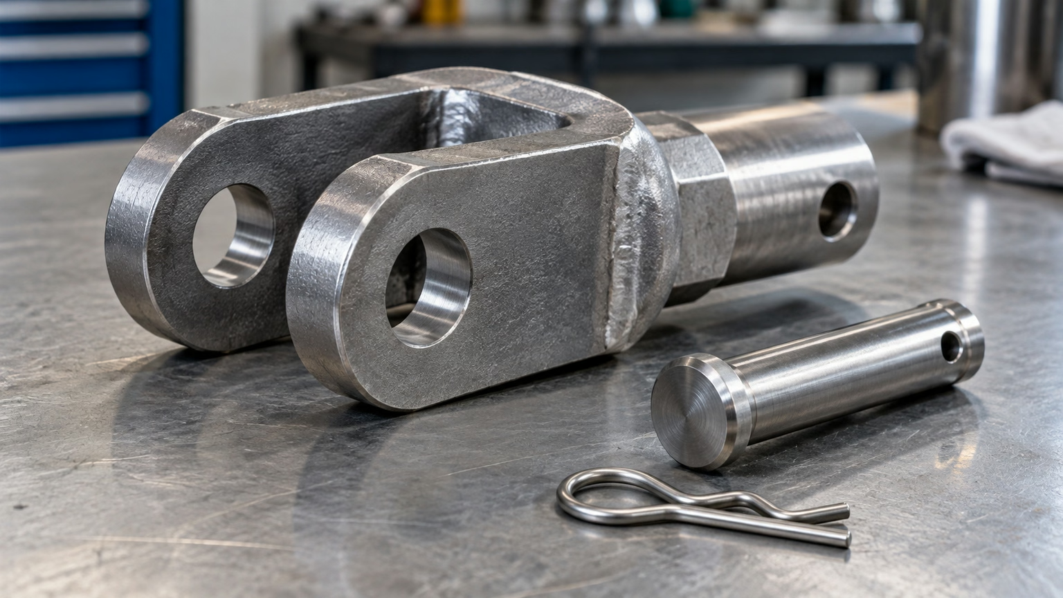
For a clevis pin design handoff, identify the finished diameter and effective grip length, the shoulder and head geometry, the finish, and the approved retention hardware. The manufacturer’s Ganter GN 2342 datasheet illustrates one family with a cross-hole for a matched spring cotter pin. Use the actual selected retainer’s drawing. [3]
Keep retention checks in the clevis pin design record alongside the section sketch. Show the installed clip or cotter orientation and the side from which a technician services it. In addition, clarify whether installation is verified on each unit or at a sample assembly stage under the agreed inspection plan.
Before issuing the drawing, check the shortest available grip and the furthest retainer position with the assembly stack at its limits. Then confirm that the retainer can be installed and removed without interference. Keep holes, grooves and threads clear of the loaded bearing and shear sections unless their effect is explicitly included in the review.
For clevis pin shear strength and pin bearing stress calculations, retain the load assumptions with the drawing revision. Specify where the diameter is measured, how the cross-hole location is referenced, and when surface condition and burrs are accepted. In addition, record the actual ear gap, alignment and retainer engagement in the assembly check where those features matter.
Use this sequence to explain how to check pin loads in a clevis pin design review. Confirm the load path first, calculate demand second, and approve allowable criteria and test requirements with the assembly owner. For component feasibility, compare the drawing with MW+’s custom machine parts scope and send critical features for CNC machining review. Share the controlled assembly interface with MetalWorksPlus.
Key takeaways
- Trace the load into both ears before assuming double shear.
- Calculate projected bearing separately at the centre link and at each ear.
- Complete the clevis pin design review with the gap, bending, retainer and assembly checks.
Frequently asked questions
Does clevis joint design always put a pin in balanced double shear?
Balanced double shear requires a load path through two effective planes and the assumed load share. Check the real geometry and engagement before applying the symmetric model. [1]
Why check the centre member and outer ears separately?
In this clevis pin design they carry different assigned forces and can have different bearing area and material properties. Calculate each member separately, then assess the actual geometry and the applicable acceptance criteria. [1]
Can I move a clip hole into a loaded section?
In a clevis pin design, a hole removes material from the section and changes the assumptions of the solid-pin calculation. Review its position and actual geometry before release, including the intended retention hardware and inspection. [1, 3]
How should I interpret the stresses from this clevis pin design example?
The numbers are calculated demands for assumed static loads and nominal geometry. Use actual loading, material evidence, limit dimensions and a design approval process to determine what the assembly can carry.