Hydraulic manifold machining turns a solid block into a pressure vessel full of intersecting passages. Most of the cost is in the drilling, but most of the failures come from what happens where the drills meet: burrs, thin walls, trapped chips and contamination. This guide covers how to choose the block material, how cartridge valve cavities and ports are cut, how cross-drilled galleries are planned and deburred, and how a manifold block is cleaned and tested before it goes into a hydraulic system.
Key takeaways
- Aluminium 6061-T6 suits most mobile and industrial manifolds at moderate pressure; ductile iron and steel take over as pressure, volume or fatigue demands rise.
- Screw-in cartridge valve cavities follow ISO 7789 or the valve maker’s drawing, and are cut with dedicated form tools so every step is concentric.
- Intersections are where manifolds fail. Burrs and chips left in galleries break loose and damage valves and pumps downstream.
- Component cleanliness is specified and verified; the fluid it protects is coded under ISO 4406.
- MW+ machines manifold blocks on multi-axis equipment with ±0.01mm to ISO 2768-m as the general tolerance and ±0.005mm on precision features.
What is a hydraulic manifold block?
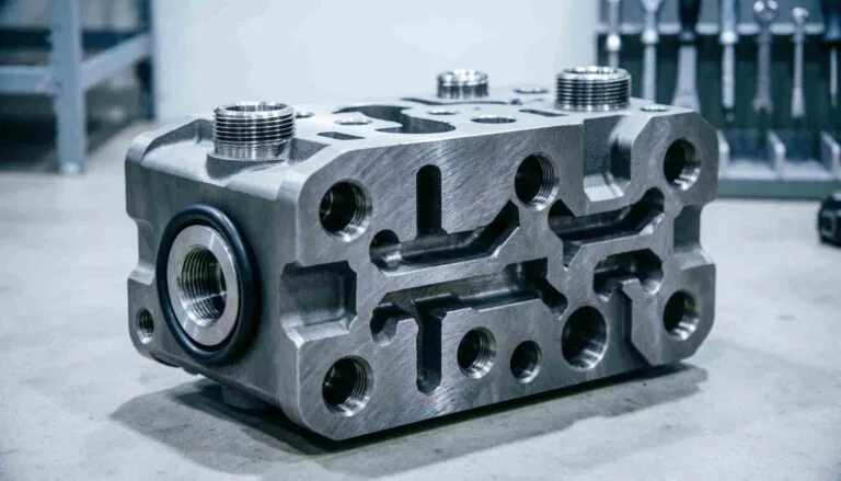
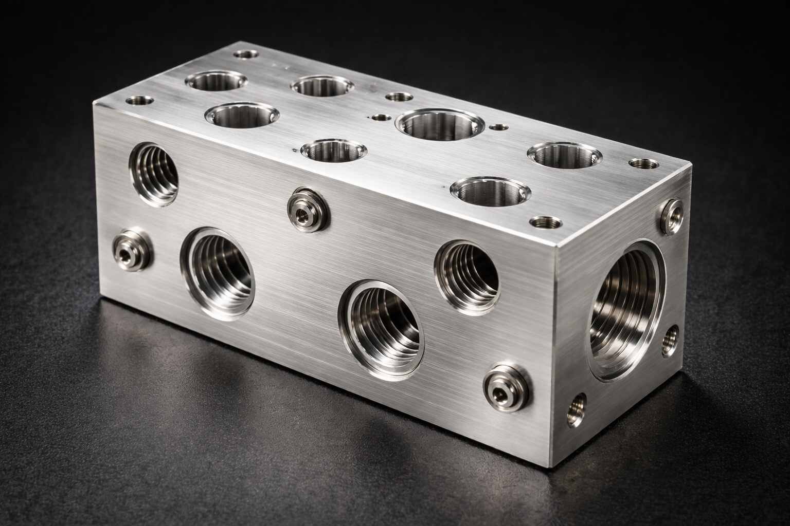
A hydraulic manifold replaces a tangle of pipes, hoses and fittings with one machined block. Valves screw or bolt into the block, and drilled passages inside it, called galleries, connect them. The result is smaller, lighter, cheaper to assemble and far less likely to leak than the equivalent plumbing.
Manifolds fall into three broad types:
- Cartridge valve manifolds, where screw-in or slip-in cartridge valves sit in cavities machined into the block.
- Subplate and modular blocks, where valves bolt onto a standard mounting face on top of the block.
- Integrated circuit manifolds, custom blocks carrying a complete hydraulic circuit for one machine, often combining both of the above.
Whatever the type, the machining problem is the same: accurate cavities and ports on several faces, joined by passages that meet exactly where the designer intended and nowhere else.
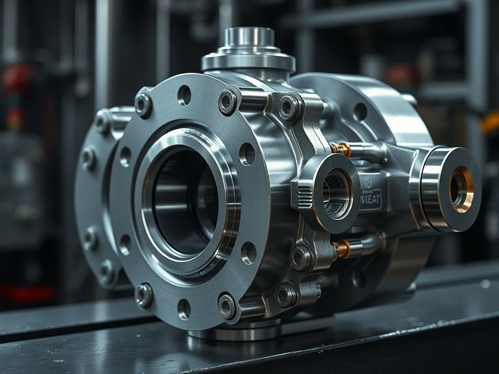
Choosing the manifold block material
The first decision in hydraulic manifold machining is the block material, and the choice balances pressure, weight, corrosion, fatigue and cost. The pressure ranges below are typical rules of thumb used by manifold designers, not limits; the actual rating comes from the design calculation and the test.
| Material | Typical working pressure | Strengths | Watch-points |
|---|---|---|---|
| Aluminium 6061-T6 | Up to about 210 bar | Light, fast to machine, anodisable | Lower fatigue strength, thread wear in soft material |
| Ductile iron | Up to about 350 bar | Damps vibration, economical at volume, good machinability | Porosity in castings or bar, needs corrosion protection |
| Carbon steel, e.g. C45 / 1045 | 350 bar and above | High strength and fatigue resistance | Heavier, slower to machine, needs plating |
| Stainless steel 316 | Application-specific | Corrosion resistance for marine, food and chemical duty | Work-hardens, slower drilling, higher cost |
Pressure pulsation matters as much as peak pressure. A block that holds a static proof test can still crack at a gallery intersection after millions of pressure cycles, which is why steel is common on high-cycle presses and mobile equipment with shock loads.
How are cartridge valve cavities and ports machined?
A cartridge valve cavity is a stepped bore: a thread at the top, then several precision diameters with sealing lands between them, each connecting to a different gallery. The valve’s O-rings seal on those diameters, so their size, roundness, concentricity and finish decide whether the valve works and whether the ports stay separate.
Screw-in cartridge valve cavities are standardised in ISO 7789, and many valve makers publish their own cavity drawings. Ports for fittings follow standards such as ISO 6149-1 for metric threads with O-ring sealing.
| Cavity or port feature | Why it matters | How it is controlled |
|---|---|---|
| Sealing diameters | O-ring squeeze and leak-free separation of ports | Form tool or reamer cutting all steps in one plunge |
| Concentricity between steps | A stepped valve must enter without cutting its seals | Single form tool, rigid holder, no re-positioning |
| Surface finish on seal diameters | Rough surfaces wear O-rings and leak | Finishing reamer or finishing pass, finish checked |
| Thread form and depth | Valve torque and retention | Thread milling or tapping, gauge checked |
| Spot face at the port | Seal seat for the fitting | Square to the port axis, burr-free edge |
Dedicated cavity form tools are the norm because they cut every diameter in one plunge, which guarantees concentricity between steps. They are an investment, so the cavity size and style should be fixed early and reused across a product family.
Cross-drilled galleries: planning the intersections
Galleries are drilled from the outside of the block, so every internal path is a set of straight holes meeting at intersections. Holes that are only there to reach an intersection are plugged afterwards. The drilling plan decides three things: whether the holes meet properly, whether the walls between them are thick enough, and how hard the intersections will be to deburr.
- Hole depth. Beyond about 10 times the diameter, standard twist drills struggle to hold straightness and clear chips. Gun drilling or peck strategies with through-tool coolant take over.
- Drill drift. Long holes wander, and the drift grows with depth. Two long holes meant to meet can miss or clip each other if the wall margin is too small.
- Intersection geometry. Holes that meet at their full diameter make clean openings. Holes that barely clip each other create thin, sharp slivers of metal that are hard to remove and easy to break off later.
- Plugs. Threaded plugs, expansion plugs and pressed ball plugs each need a specific hole form and finish.
Worked example: a first check on the wall between a gallery and the outside
A quick sanity check on wall thickness uses the thin-wall pressure formula t = P × D ÷ (2 × S), where P is pressure, D is the passage diameter and S is the allowable stress.
- Take a Ø10mm gallery at 250 bar, which is 25 MPa, in 6061-T6 aluminium.
- 6061-T6 has a minimum yield strength of about 240 MPa. With a safety factor of 4, the allowable stress S is 60 MPa.
- t = 25 × 10 ÷ (2 × 60) = 2.1mm.
That is a starting point, not a design. Real manifolds add margin for drill drift on long holes, for stress concentration at intersections and for fatigue under pulsating pressure, which is why designers commonly leave several millimetres more. A useful habit is to ask the machinist how far a hole of that length is likely to drift, and add it.
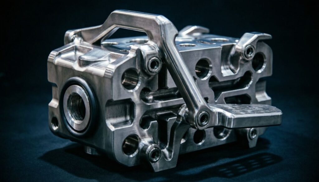
Deburring the intersections
A burr at a gallery intersection is invisible from outside, hard to reach, and dangerous. If it breaks free in service, it travels to the tightest clearance in the system, usually a valve spool or pump, and damages it. Deburring is therefore a controlled step in hydraulic manifold machining, with its own method and inspection.
| Method | How it works | Best for | Limits |
|---|---|---|---|
| Manual deburring | Brushes, scrapers and probes worked through the ports | Prototypes, accessible intersections | Operator-dependent, slow, hard to verify |
| Back-deburring tools | A tool passes through the hole and cuts the far edge | Straight-through holes | Needs access from one side and space for the blade |
| Thermal deburring | A gas mixture is ignited in a sealed chamber and burns off thin burrs | Volume production, hidden intersections | Affects all thin edges, oxide film to remove |
| Electrochemical deburring | An electrode dissolves burrs at a defined location | Repeatable deburring of specific intersections | Electrode per geometry |
| Abrasive flow machining | Abrasive paste is pushed through the passages | Radiusing intersections, improving internal finish | Cost, cleaning of media afterwards |
Cleanliness and contamination control
Hydraulic systems are specified by fluid cleanliness, coded under ISO 4406. A new manifold that sheds chips and burrs into that fluid on first start-up undoes the whole filtration strategy. That is why component cleanliness is specified and verified separately.
ISO 18413 covers how cleanliness of hydraulic components is inspected and reported, and automotive programmes often use ISO 16232. In practice, a clean manifold block comes from four habits:
- Flushing every gallery individually, not just washing the outside of the block.
- Directed high-pressure washing into each port, with the block turned so chips can fall out.
- Drying completely, because residual water corrodes steel and iron blocks from the inside.
- Capping every port immediately after cleaning and packing the block so the caps stay on.
Surface treatment and protection
Aluminium blocks are often anodised, and steel and iron blocks are plated or phosphated. The coating matters, but so does what it must not touch. Sealing diameters, threads and cavity steps are usually masked, because coating build-up changes their size and can flake into the circuit. Our guide to metal surface finishing compares the options.
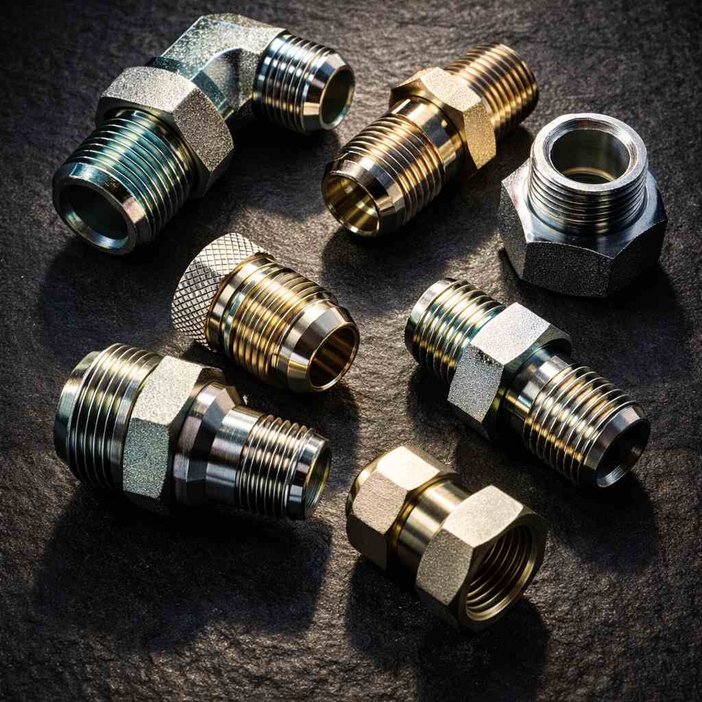
6 critical steps in hydraulic manifold machining
1. Confirm material and pressure rating
Agree the alloy, its condition and the design pressure before quoting. The material certificate is checked against the drawing on receipt.
2. Plan datums and setups
A manifold has features on up to six faces. The fewer times it is re-clamped, the better galleries line up. Multi-axis machines let most faces be cut from one set of datums.
3. Cut cavities with form tools
Cartridge valve cavities are cut with dedicated form tools and finished to the specified diameters and surface finish, with the first cavity of each batch checked before the rest are cut.
4. Drill galleries to a written plan
Depths, drilling strategy and intersection points are planned from the model, with deep holes gun-drilled or peck-drilled with through-coolant to control drift.
5. Deburr and clean every passage
Intersections are deburred by the agreed method and inspected, then every gallery is flushed, dried and capped.
6. Test and document
Blocks are pressure or leak tested where the drawing requires it, commonly at a proof pressure above the working pressure set by the designer. Every order ships with a certificate of conformance, a CMM report and material certificates.
Common hydraulic manifold defects and how to prevent them
Most rejected blocks fail for a small number of reasons, and almost all of them are decided before the first cut. The table lists the defects we look for in DFM review and at inspection.
| Defect | Usual cause | Prevention |
|---|---|---|
| Leak between two ports | Wall between galleries too thin after drill drift | Wall margin that allows for drift, drilling strategy for long holes |
| Valve leaks or sticks in its cavity | Sealing diameters out of size, poor finish or steps not concentric | Dedicated form tools, first-cavity check each batch, finish verified |
| Contamination at first start-up | Chips and burrs trapped in galleries | Intersection deburring, gallery-by-gallery flushing, ports capped |
| Crack at an intersection after service | Sharp intersection edges acting as stress raisers under pulsation | Full-diameter intersections, radiused edges, material chosen for fatigue |
| Fitting leak at a port | Spot face not square or damaged, burr on the port edge | Spot face cut in the same setup as the port, edges inspected |
| Plug blows out under test | Wrong hole form or finish for the plug type | Plug type and hole form specified on the drawing |
The pattern is the same as in most precision work. Where a manifold block fails, it is rarely because a machine could not hold a dimension. It is because the drilling plan, the deburring method or the cleaning step was left to chance. Good hydraulic manifold machining treats those three steps as engineered processes with their own checks, not as housekeeping at the end of the job.
When is machining the wrong way to make a manifold?
- Very simple circuits. Two or three valves in line may be cheaper plumbed with tube and fittings than built into a custom block.
- High volumes. At thousands of identical blocks a year, a casting with cored passages and machined cavities can beat drilling from solid.
- Flow-critical or weight-critical designs. Additively manufactured manifolds with curved internal channels reduce pressure drop and weight, with machining used for the cavities and interfaces.
How MW+ machines hydraulic manifold blocks
MW+ is a precision CNC machining company in Shenzhen. Hydraulic manifold machining at MW+ runs through our CNC milling services, with complex multi-face blocks on multi-axis machining centres so galleries start from common datums. Blocks for complete machines are often supplied alongside shafts, housings and brackets through our machine parts manufacturing service.
For a related example of cross-hole deburring and technical cleanliness in production, read our EV housing machining case study. For inspection, our guide on tolerance stack-up explains why setup count matters on multi-face parts.
Frequently asked questions
Which material is best for a hydraulic manifold?
6061-T6 aluminium for most moderate-pressure industrial and mobile blocks, ductile iron for economical higher-pressure blocks at volume, and steel where pressure, shock or fatigue demands it. Stainless steel is for corrosive environments. Tell us the working pressure and environment and we will suggest the most economical option.
Can you machine cartridge valve cavities to the valve maker’s drawing?
Yes. Send the valve maker’s cavity drawing or the ISO 7789 designation, and we will cut the cavities with form tools and check the first cavity of each batch before completing the rest.
How do you make sure there are no burrs inside the manifold?
By planning intersections to avoid slivers, deburring by an agreed method, and inspecting intersections with magnification or an endoscope where access allows. Every gallery is then flushed individually during cleaning.
Do you pressure test manifold blocks?
Where the drawing specifies it, yes. Tell us the test pressure, medium, hold time and acceptance criterion so the test is planned into the route and recorded in the documentation.
How deep can you drill galleries?
Deep galleries are drilled with gun drills or peck-drilling strategies with through-tool coolant. The practical limit depends on diameter and material, and we review deep holes and their drift allowance at the DFM stage.
Can you plug galleries?
Yes, with threaded plugs, expansion plugs or pressed ball plugs, as specified. Each needs a particular hole form, so plug type should be on the drawing.
What tolerances do you hold on manifold blocks?
±0.01mm to ISO 2768-m generally, with ±0.005mm on precision features such as cavity sealing diameters where specified. Port positions are held relative to the block’s datums.
How long does it take to machine a hydraulic manifold?
Prototype blocks typically take 3 to 5 business days, and production batches 10 to 15 business days. Deep galleries, many cartridge valve cavities, finishing and pressure testing all add time, so the quote states the lead time for your specific manifold block rather than a general figure.
What to send us
A STEP model with internal passages, the drawing with cavity and port specifications, the material, the working and test pressures, the cleanliness and finishing requirements, and the quantity. You will get a quote and written DFM feedback within 24 hours, including a review of the drilling plan and intersections in your hydraulic manifold machining job.