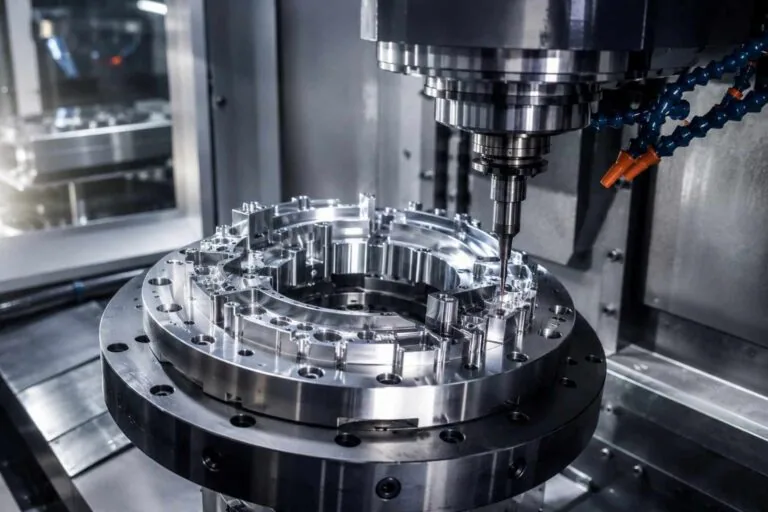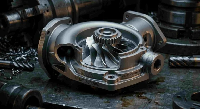
Impeller machining is where 5-axis equipment earns its price. This case study covers 5-axis impellers for a US aerospace OEM, held to ±0.005mm concentricity and delivered in 4 days, where the DFM feedback on the drawing cut the client’s tooling cost by 20%. It walks through why aerospace impellers need simultaneous 5-axis motion, where the tooling saving came from, and how concentricity at that level is machined and proven.
Project at a glance
- Industry
- Aerospace OEM
- Client
- Procurement manager, United States
- Part
- Impellers
- Process
- Simultaneous 5-axis milling
- Tolerance
- ±0.005mm concentricity
- DFM outcome
- Tooling cost down 20%
- Delivery
- Parts arrived in 4 days
- Result
- “Beyond expectations” (client)
- ±0.005mmconcentricity on the finished impellers
- 20%lower tooling cost after DFM feedback
- 4 daysfrom order to parts arriving
- 5-axissimultaneous machining in one setup
“MW+ delivered 5-axis impellers with ±0.005mm concentricity, beyond expectations. Their DFM feedback saved us 20% on tooling costs and the parts arrived in 4 days.”
Procurement Manager, Aerospace OEM, United States
Why does impeller machining need simultaneous 5-axis?
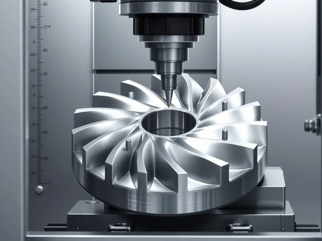
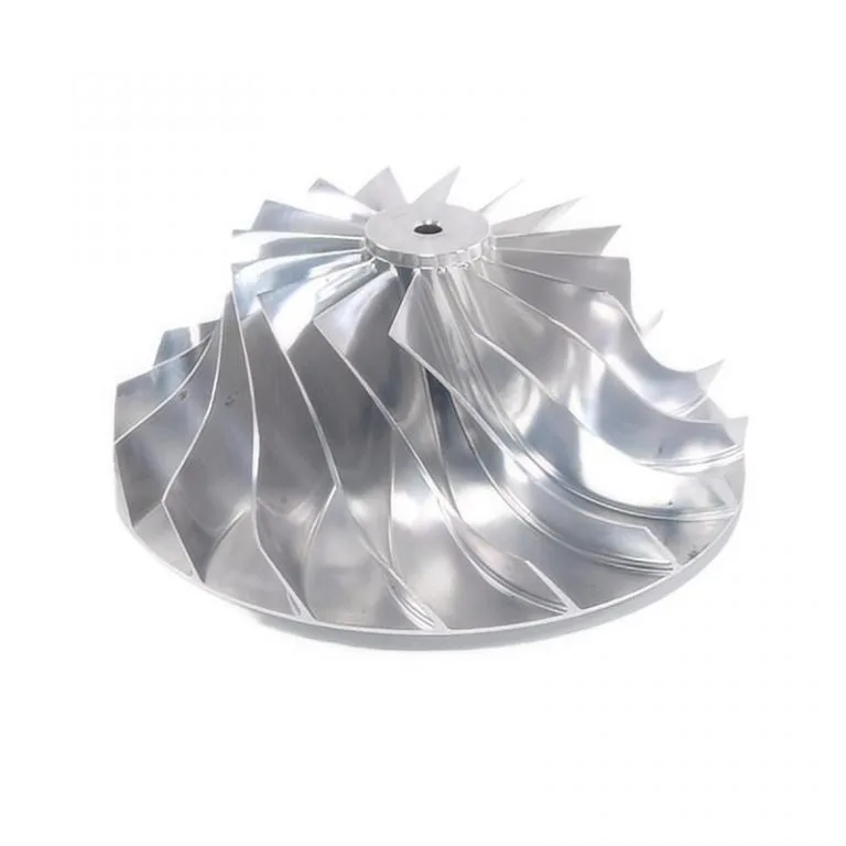
An impeller is a hub with a set of twisted blades wrapped around it. The blades lean, curve and change thickness from root to tip, and the passages between them narrow toward the hub. Often there are splitter blades between the main blades, which narrows the gap further.
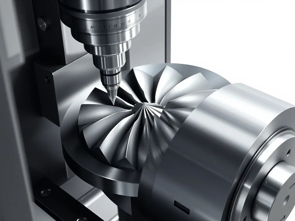
A 3-axis machine can only point the tool straight down. It cannot reach under a leaning blade or follow a twisted surface without gouging the next blade. Even 3+2 indexed machining, where the part is tilted and locked, leaves steps on a continuously curved blade. The tool axis has to move while it cuts, tilting to stay clear of the neighbouring blade and normal to the surface being finished. That is simultaneous 5-axis machining, and impellers are the classic part that requires it.
In short, blade machining on an impeller is a problem of access, stiffness and datum at the same time, and 5-axis impellers are made the way they are to solve all three.
Our explainer on how 5-axis machining works covers the machine side. This page is about what it takes to turn that capability into a good impeller.
What makes blade machining difficult
- Access. The tool must fit between blades without touching either one, which limits its diameter and forces long reach.
- Stiffness. A long, thin tool deflects. A thin blade deflects too. Two flexible objects meeting produce chatter.
- Surface. Blade surfaces carry the flow, so scallop height and tool marks matter aerodynamically, not just cosmetically.
- Datum. Every blade must sit true to the bore and the axis, or the impeller will run out of balance.
What the client asked for
The request came from the procurement manager of an aerospace OEM in the United States. Three things were in the brief: concentricity of ±0.005mm, a lower total cost than the programme had budgeted, and parts fast. Client names, part numbers and alloy details are not published.
| Requirement | Why it matters on an impeller | How it was addressed |
|---|---|---|
| ±0.005mm concentricity | Blade-to-axis error becomes unbalance and vibration | Bore and blades referenced to one datum, no re-chucking |
| Blade profile to model | Flow performance depends on blade shape | Simultaneous 5-axis finishing, CMM profile check |
| Controlled blade surface finish | Surface roughness affects efficiency and fatigue | Finishing strategy and stepover set per surface zone |
| Lower tooling cost | Special tools dominate impeller cost at low volumes | DFM review focused on tool-driving features |
| Fast delivery | Programme schedule | DFM, CAM and fixture planned together, express shipping |
The DFM review: where a 20% tooling saving comes from
On aerospace impellers at prototype and low volumes, tooling is often the biggest single cost after machine time. The expensive tools are the special ones: tapered ball-nose cutters with a non-standard tip radius, extra-long reach tools, and form cutters made for one fillet. A DFM review that removes the need for even one special tool can move the whole quote.
The client credited our DFM feedback with a 20% saving on tooling. The table below lists the features our DFM review checks on every impeller drawing, because these are the ones that decide which tools a job needs. It is the checklist, not a record of the client’s specific changes, which are not published.
| DFM check | Why it drives tooling cost | Typical recommendation |
|---|---|---|
| Hub-to-blade fillet radius | A radius between standard tool sizes forces a special cutter | Allow a radius that matches a standard tapered ball tool, or a tolerance that covers one |
| Narrowest gap between blades | Sets the maximum tool diameter and so tool stiffness | Confirm the gap at the hub, check whether splitter length can change |
| Blade depth versus gap | Sets tool reach; long-reach tools cost more and cut slower | Check whether reach can be shortened by approach angle |
| Leading and trailing edge form | Full radii on thin edges may need small, fragile tools | Agree edge form and tolerance with the aerodynamic owner |
| Surface finish per zone | A single tight finish everywhere multiplies finishing passes | Tight finish on blade surfaces, relaxed on the hub rear and bore chamfers |
| Datum scheme | An awkward datum needs a special fixture | Datum on the bore and back face, turned in one setup |
The discipline that matters is to change only what the part’s function allows. Every recommendation goes back to the client’s engineers for approval, because the aerodynamic owner of an impeller knows which surfaces are critical and which are merely drawn that way. This is where most of the saving in impeller machining is found: before the first cut, not during it.
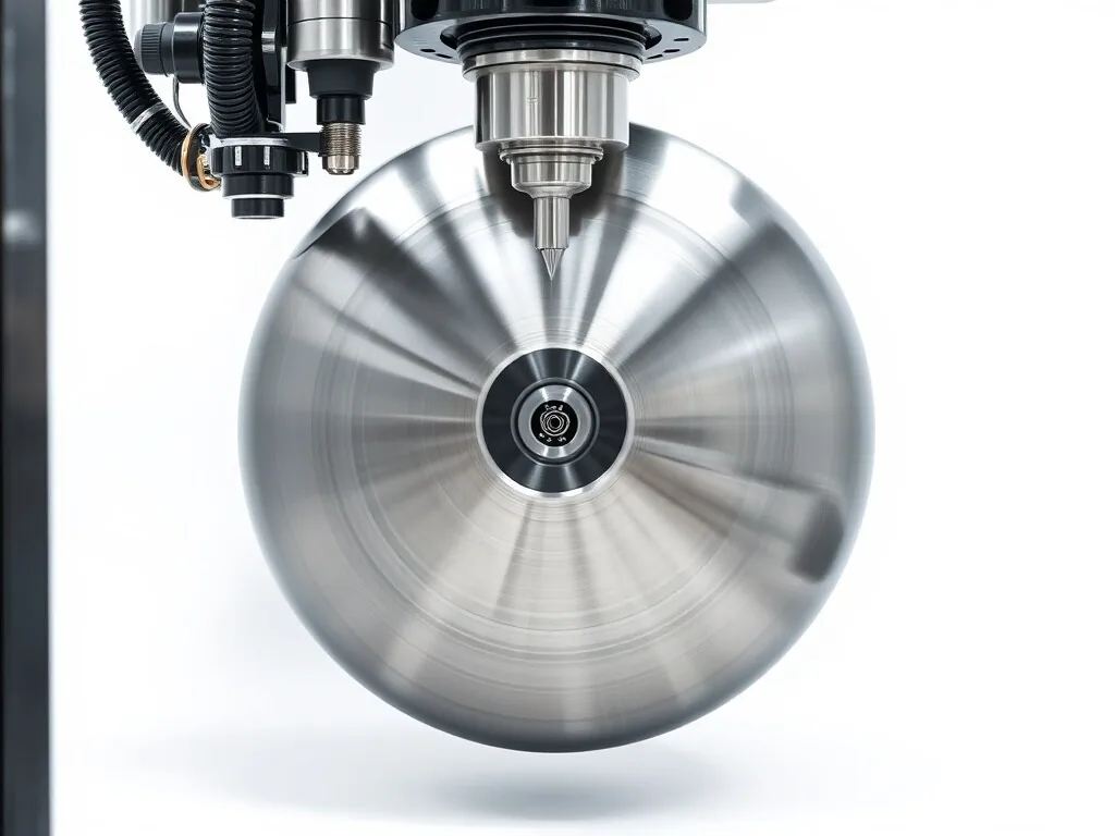
The 5-axis impellers machining route
The route below is how MW+ runs 5-axis impellers of this type on the equipment described on our multi-axis machining page. The principle is one datum, established early and never lost.
| Step | Operation | What it controls |
|---|---|---|
| 1 | Turn the blank: hub profile, bore and back face in one chucking | The datum axis and face every later feature refers to |
| 2 | Mount on a fixture that locates on the bore and back face | Transfers the datum to the 5-axis machine without new error |
| 3 | Rough the blade passages | Removes most material while leaving an even allowance |
| 4 | Semi-finish blades and hub | Evens out stock so the finish pass cuts at constant load |
| 5 | Finish blades, splitters and hub fillets with simultaneous 5-axis motion | Blade profile and surface finish |
| 6 | Edge break and deburr at leading and trailing edges | Edge form without rounding the profile |
| 7 | Inspect on CMM: bore, runout, blade sections | Concentricity and profile against the model |
Point milling or flank milling?
There are two ways to finish a blade. Point milling uses the tip of a ball-nose tool and traces the surface in many passes. It handles any blade shape, but it leaves scallops and takes time. Flank milling, also called swarf cutting, lays the side of a tapered tool along the blade and finishes it in far fewer passes. It is faster and leaves a smoother surface, but only works when the blade surface is ruled, meaning it can be swept by a straight line. Many impeller blades are designed to be ruled for exactly this reason. Checking that at the DFM stage is one of the quickest ways to cut both cycle time and tool wear in blade machining.
Holding ±0.005mm concentricity
Concentricity is the tolerance the client named, and it is worth being precise about it. ISO 1101 defines concentricity and coaxiality as the location of a centre point or axis relative to a datum. The 2018 edition of ASME Y14.5 removed concentricity altogether, and most US drawings now express the same intent with circular or total runout, or with position.
Whatever the symbol, the answer in impeller machining is the same. The bore, the back face and the blades must all be produced relative to one axis. That is why the bore and back face are turned in a single chucking, and why the 5-axis fixture locates on them rather than on the outside of the blank.
Worked example: why 5 µm of eccentricity matters to balance
Balance quality for rigid rotors is set by ISO 21940-11. The permissible specific unbalance, in g·mm per kg, which is the same number as the allowed offset of the centre of mass in micrometres, is:
e_per = 9549 × G ÷ n, with G the balance grade in mm/s and n the service speed in rpm.
Take an impeller balanced to grade G2.5, a common grade for turbomachinery rotors, running at 30,000 rpm:
- e_per = 9549 × 2.5 ÷ 30,000 = 0.80 µm
- For a 0.5 kg impeller, the permissible residual unbalance is 0.5 × 0.80 = 0.40 g·mm
- If the whole blade and hub mass sat just 5 µm off the bore axis, the specific unbalance would be about 5 µm, more than six times the limit
The point is not that concentricity replaces balancing. High-speed impellers are still balanced. The point is that the closer the machining holds concentricity, the less correction the balancer has to make, and the less material has to be removed from places the designer did not intend.
The inspection plan for aerospace impellers
Aerospace work at MW+ runs under our AS9100D quality system. Every order ships with a certificate of conformance, a CMM report and material certificates, and first article inspection to AS9102 is available on request.
| Characteristic | Method | Notes |
|---|---|---|
| Bore diameter and form | CMM or bore gauge | Measured first, since everything refers to it |
| Concentricity or runout of blade tips to bore | CMM with the bore as datum | Reported against the drawing’s callout |
| Blade section profile | CMM scanning at defined sections | Compared with the CAD model |
| Blade thickness at root and tip | CMM | Thin edges checked for over-cut |
| Hub fillet radius | Optical or CMM | Confirms the agreed tool radius was used |
| Surface finish on blade faces | Profilometer where accessible | Per zone, as agreed at DFM |
How a 4-day impeller machining turnaround is planned
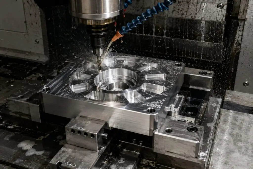
The client’s parts arrived four days after the order. Our standard prototype window is 3 to 5 business days, with a 48-hour express route for simple parts, and an impeller sits at the demanding end of that window. These are the conditions that make it possible.
- DFM and CAM overlap. Toolpaths are built while the DFM points are with the client, so approval releases the job straight to the machine.
- Standard tools where possible. The same DFM changes that cut tooling cost also remove the wait for special cutters.
- One fixture, designed with the part. A bore-and-face fixture is quick to make and reusable for repeat orders.
- Inspection planned in advance. The CMM programme is written from the model before the part is finished.
- Express shipping. Door-to-door air freight to the United States is typically 2 to 5 business days, so fast manufacturing only helps if dispatch is same-day.
The result
The client received 5-axis impellers with ±0.005mm concentricity, which the procurement manager called beyond expectations. The DFM feedback saved 20% on tooling, and the parts arrived in 4 days. Those three figures are the client’s own, as published on our homepage, and they are the only outcome claims this page makes.
About this case study. The client quote is published on our homepage as given. Client name, part numbers, alloy and quantities are not published. The DFM checklist, route and inspection plan describe how MW+ approaches impeller machining.
How to specify aerospace impellers so they are cheaper to make
- Use runout or position rather than concentricity if your drawing follows ASME Y14.5-2018. It is easier to measure and means the same thing to the machinist.
- Give fillet radii a tolerance that covers at least one standard tool size.
- Design blades as ruled surfaces where the aerodynamics allow it, so they can be flank milled.
- Specify finish by zone. Blade surfaces and the hub rear rarely need the same roughness.
- State the balance grade and service speed so the supplier can judge how much concentricity really matters.
- Tell the supplier the alloy early. Aluminium, titanium and nickel alloys need different tools, speeds and cycle times; our Inconel 718 machining guide covers the hardest case.
When 5-axis impeller machining is the wrong choice
Impeller machining from solid is the right route for prototypes and low volumes. It is not always the right route for aerospace impellers in production.
- High-volume production. At thousands of pieces a year, a cast or forged impeller with machined bore, faces and critical surfaces is usually cheaper than machining every blade from solid.
- Closed (shrouded) impellers. A cover over the blade passages blocks tool access. These are made as two machined halves joined together, by electrical discharge machining of the passages, or by additive manufacturing with machined interfaces.
- Very small impellers. Below a certain size, blade gaps are narrower than practical 5-axis tools, and micro machining techniques take over.
Frequently asked questions
What tolerance can you hold on 5-axis impellers?
We held ±0.005mm concentricity for this client, and ±0.005mm is our standard precision band for 5-axis work, with ±0.001mm possible on selected features. Blade profile tolerance depends on size, alloy and blade thickness, and we confirm it feature by feature at the DFM stage.
Which alloys can you use for aerospace impellers?
Aluminium alloys, titanium alloys, stainless steels and nickel alloys such as Inconel 718 are all machined on the same 5-axis equipment. Cycle time and tooling cost rise sharply from aluminium to titanium to nickel alloys, so the alloy is the first thing to confirm.
Do you balance impellers?
Tell us the balance grade and service speed on the drawing. We machine to hold concentricity so that balance correction is minimal, and we will confirm at quote stage how balancing to your grade is handled for your part.
How long does impeller machining take?
Prototype impellers typically take 3 to 5 business days to manufacture, depending on alloy and blade count, plus shipping. This client’s parts arrived in 4 days. Production batches are planned at 10 to 15 business days.
Can you machine closed impellers?
A fully shrouded impeller cannot be milled from solid in one piece because the cover blocks access. We can discuss two-piece machined designs, EDM routes or machining the interfaces of an additively built part.
What documentation comes with aerospace impellers?
Every order includes a certificate of conformance, a CMM report and material certificates. First article inspection to AS9102 is available on request and quoted per programme.
What do you need to quote impeller machining?
A STEP model, a drawing with datums, the alloy, the quantity, the balance grade and service speed if known, and any surface finish requirements by zone. An engineer returns a quote and written DFM feedback within 24 hours.
Have an impeller to quote?
MW+ is a precision CNC machining company in Shenzhen with 60+ multi-axis CNC machines and CMM inspection in one facility, certified to AS9100D. If you are sourcing impellers, blisks or other blade machining work, our 5-axis supplier audit checklist is a good way to test any shop, including ours, and our CNC precision parts range shows the wider work.
Send the model and drawing. You will get a price, a lead time and DFM feedback within 24 hours, with the tool-driving features of your impeller machining job flagged before they cost you money.