







Retaining ring groove design starts with the exact ring family and part number. Use the ring maker’s drawing to set the shaft and groove dimensions. Then review the axial stack, load path and installation access. A groove that accepts the ring can still leave too much end movement or too little material behind the loaded wall. [1, 2]
Illustrative application guide. This worked example uses published dimensions for one external Smalley ring. The adjacent component and its location are illustrative. The exercise shows how to specify a ring groove for review. It supplies no qualified load rating or customer result.
Retaining ring groove design begins with the load path
In this example, a sleeve slides onto a shaft until it reaches a fixed shoulder. An external ring on the other side of the sleeve limits its axial travel. In a retaining ring groove design review, sketch the shoulder, sleeve face, ring and loaded groove wall together. Mark the expected thrust direction. If thrust can reverse, describe the parts that carry it in each direction.
The Smalley WS-100 product schematic and specifications identify an external medium-duty two-turn spiral retaining ring for a nominal 1.000 in shaft. We use this family for the worked example. Similar nominal shaft diameters do not establish interchangeability. Keep the selected part number and material variant with the controlled drawing. [1]
For retaining ring groove design, before using a snap ring groove from another drawing, match the associated ring and shaft requirements. A turned groove marked only with a nominal diameter leaves width, corner condition and position open. A retaining ring groove design for a replacement shaft should also identify the existing ring and the drawing that governed its original installation.
Smalley’s design guidance separates ring shear from groove deformation and highlights the groove material, geometry and remaining edge margin. It also identifies dynamic or eccentric loads as outside its basic capacity model. Therefore, document the axial load and its service conditions independently of the dimensional example below. [2]
Snap ring groove dimensions for the selected shaft
Compare groove width with the ring thickness limits
For retaining ring groove design, read the published groove width and ring thickness separately. Then use the minimum width and maximum thickness to screen for a tight fit. Reverse the limits to screen the greatest nominal axial float of an ideal ring in an empty groove. Real seating also depends on the geometry of the ring and both groove walls. [1, 2]
| Characteristic | Manufacturer entry | Use in this example |
|---|---|---|
| Shaft diameter Ds | 1.000 | Nominal reference. The example assigns no shaft fit tolerance. |
| Groove diameter Dg | 0.957 ± 0.003 | Interval 0.954–0.960. |
| Axial groove width w | 0.042 +0.003/−0.000 | Interval 0.042–0.045. |
| Ring thickness t | 0.037 ± 0.002 | Interval 0.035–0.039. |
| Calculated width clearance w − t | Derived from the two published intervals. | Minimum 0.042 − 0.039 = 0.003. Maximum 0.045 − 0.035 = 0.010. |
For the retaining ring groove design depth check, use d = (Ds − Dg)/2. At the published nominal shaft and groove diameters, the result is 0.0215 in. Holding the shaft diameter at 1.000 in and varying only the groove diameter gives 0.020–0.023 in. Once the approved shaft limits are known, use the smallest shaft with the largest groove for minimum radial depth, and the opposite pair for maximum depth.
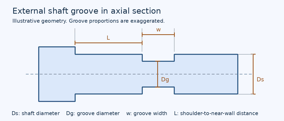
Next, check where the ring meets the groove walls. A snap ring groove drawing should tell inspection which surfaces establish seating. A gauge can show an acceptable groove width at one radial height while a corner radius or burr reduces usable seating elsewhere. Use Smalley’s model-specific requirements and corner guidance, and confirm the applicable configuration with the manufacturer before release. [1, 2]
Set groove location from the functional shoulder
For a hypothetical shaft retaining ring groove, assume the near groove wall is 0.626 ± 0.001 in from the fixed shoulder, and the sleeve length from the shoulder to its end face is 0.620 ± 0.002 in. These are assumed drawing inputs. The groove wall nearest the sleeve is a reference for calculation.
In this retaining ring groove design, the geometric gap from sleeve to near wall is L − S. At minimum it is 0.625 − 0.622 = 0.003 in. At maximum it is 0.627 − 0.618 = 0.009 in. If an ideal unpreloaded ring translates from contact at the near wall toward the far wall through its full width clearance, the maximum geometric gap to the ring face becomes 0.009 + 0.010 = 0.019 in.
Therefore, a retaining ring groove design can need a separate axial-position requirement even when the groove itself meets the catalog limits. Treat the 0.019 in value as a simplified upper envelope for this geometry. It excludes deflection, tolerances on faces not modeled, and actual ring behavior. Confirm how the ring sits under the intended load rather than treating this as a measured endplay or an approved result.
If the retaining ring groove design depends on a small clearance, identify which dimension consumes most of the travel budget. For example, changing the location tolerance affects the gap to the near wall. A width change affects the ring’s potential float and must be reviewed against the approved ring detail.
Also check the land from the loaded groove wall to the shaft end or the next relief. In a retaining ring groove design close to a free end, shortening this land changes the material available to support axial load. Show the sleeve’s contacting corner and check access for installation and removal. Use the rings and intended assembly tools during the fit check. [2]
Specify the groove and the inspection record together
Before releasing the retaining ring groove design, agree how the supplier will inspect the bottom diameter at the available width. Ask which contact geometry can reach the groove bottom without riding on the radii. Then identify where the width is measured and whether axial position references the fixed shoulder, the near wall, the far wall or another explicitly dimensioned surface.
| Feature | Requirement owner | Evidence to request |
|---|---|---|
| Shaft and groove bottom diameters | Assembly drawing and selected ring specification. | Actual diameters, units and measurement method. Identify the location and contact geometry. |
| Width and corner condition | Ring documentation and approved groove detail. | Width readback and agreed corner or profile check at usable seating surfaces. |
| Near-wall axial location and end land | Assembly drawing and load review. | Axial position relative to the fixed shoulder and remaining land past the loaded wall. |
| Installed condition | Assembly owner and ring installation requirements. | Confirm complete seating, tool access and sleeve travel by the agreed inspection method. |
For a retaining ring groove design handoff, record the shaft material and condition beside the part number and load case. Confirm the groove’s final state after any surface treatment. For example, if the groove is finished before coating, tell inspection whether acceptance is required before or after coating and which evidence governs the assembled fit.
When checking a retaining ring groove design from a supplier’s drawing, ask for the groove detail and inspection plan together. A drawing can repeat the catalog width accurately while leaving the measurement location or assembly acceptance open. Close those decisions before approving the first-article plan.
To decide how to specify a ring groove for production, bring the current ring document, assembly drawing and load assumptions to a CNC machining review. Include mating shaft and sleeve details and identify the measurements that matter to the assembler. Share the controlled revision with MetalWorksPlus to discuss tool access and first-article reporting.
Key takeaways
- Choose the exact ring before dimensioning its groove.
- For retaining ring groove design, calculate radial depth, ring-to-wall clearance and assembly travel separately.
- Before finalizing the retaining ring groove design, review the loaded wall, end land and installation conditions with the ring manufacturer and assembly owner.
Frequently asked questions
Are all external snap ring grooves identical?
Different rings can call for different dimensions even when the nominal shaft diameter is the same. Match the type, exact part number and material option before using a catalog dimension. [1, 2]
How do I calculate the depth of a shaft retaining ring groove?
For a concentric external groove, subtract the groove diameter from the shaft diameter and divide by two. A production depth range should use the approved diameter limits for both surfaces.
Can I use a generic groove detail in place of the ring drawing?
Use the ring manufacturer’s dimensional requirements and put any application-specific position, end land, surface and inspection limits on the controlled shaft drawing. Generic dimensions cannot confirm compatibility with a chosen ring. [1, 2]
Does the catalog load rating qualify the finished assembly?
The assembled shaft and sleeve need their own assessment. In a retaining ring groove design review, verify ring shear, groove material and deformation, surrounding geometry and the actual loading conditions. Consult the manufacturer where impact, eccentric loading or rotation affects the application. [2]