







Sheet metal tab and slot design starts by assigning each locating feature a job. Seat the parts against a stable reference, choose a primary tab to control position, and give the second tab room to accommodate spacing variation. Calculate clearance from the limits of both mating features. Then check the dry fit and the assembly after welding.
Illustrative application guide. The example uses a laser-cut upright, a slotted base and a removable machined stop. Dimensions are hypothetical and in millimetres. They illustrate fit-up arithmetic and inspection decisions. No customer project, measured result, weld qualification or MW+ process tolerance is implied.
Sheet metal tab and slot design: assign the locating features
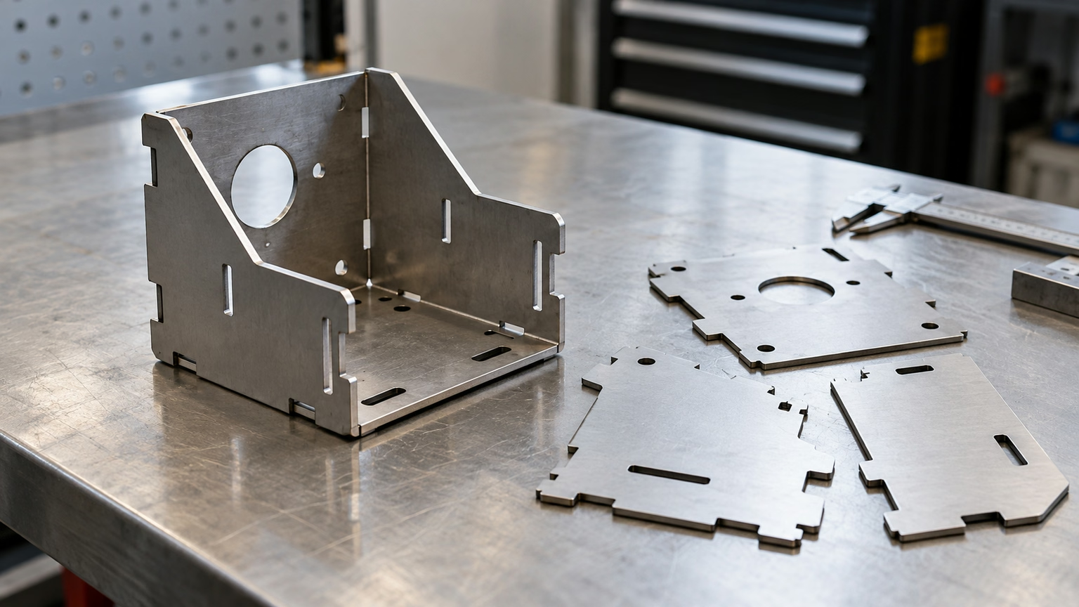
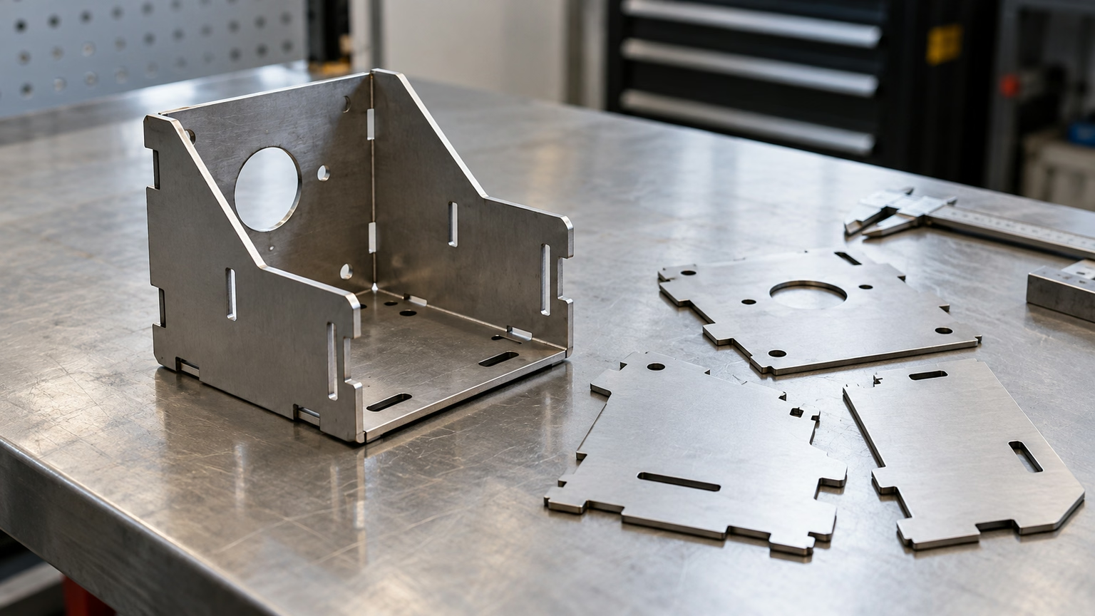
For sheet metal tab and slot design, first sketch how the pieces meet and which surfaces must touch. In this example, the upright shoulder seats against the base. The side of a primary slot limits movement along the line between the tabs. Two slot faces transverse to that line help limit rotation once the upright is clamped.
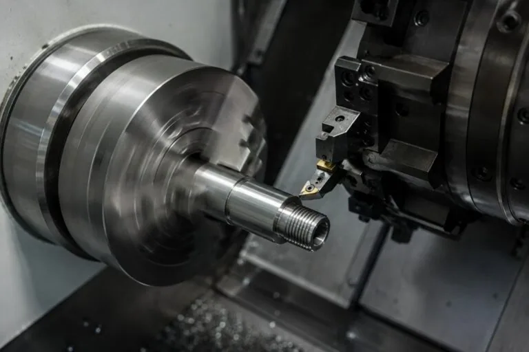
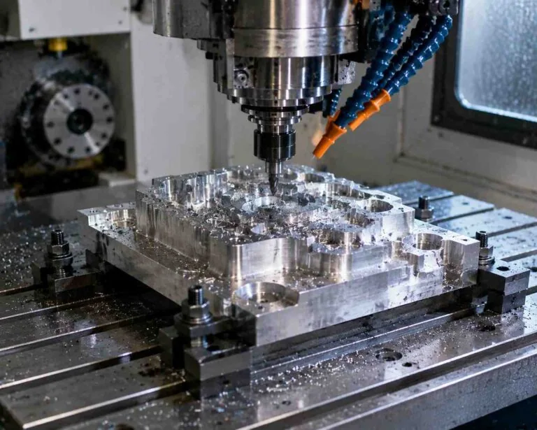
Next, identify the surface that controls the assembled dimension. Here, the base sits against a removable machined stop that registers a functional edge. The tabs assist loading and repeatable orientation. Inspect the finished location from the specified reference on the assembly drawing, with the fixture removed when the acceptance condition is free-state.
In a practical sheet metal tab and slot design, an unequal tab width or offset can also make the intended orientation obvious. SendCutSend’s fabrication guide [1] shows how tab geometry can distinguish mating positions and recommends considering the actual assembly path.
However, an orientation feature needs its own clearance review. Try the correct and reversed configurations in the model. Check that the correct tab enters fully and the wrong arrangement stops before the parts appear seated. Then ask whether the operator can see the seating surface with clamps installed.
Laser cut tabs, slot ends and the insertion path
When drawing laser cut tabs, distinguish three dimensions: tab width in the flat pattern, stock thickness through the tab, and protrusion into or through the receiving panel. Each dimension answers a different question about insertion, side play or access to the joint.
For sheet metal tab and slot design near a formed flange, review the geometry after bending as well as the flat pattern. Protolabs’ fabrication guide [2] explains how bends can deform nearby slots and how narrow slots may be hard to cut. Ask the fabricator to confirm its limits for the proposed material, tooling and geometry.
Also, check entry and exit corners on laser cut tabs. Specify functional edge conditions on the drawing and ask the fabricator to review them. For example, a proposed lead-in can help insertion, but a rounded inside corner can still meet a square tab root before the shoulder reaches the base.
For this sheet metal tab and slot design, draw a section through the tab root and receiving edge. Check the corner relationship at both sheet faces and include the intended insertion angle if the upright must be tipped into the slot. In a closed enclosure, verify the path with any neighbouring flange already in place.
Finally, identify the manufacturing condition used for acceptance. If parts mate after coating, a deposited layer on the tab enlarges its envelope while a layer on opposing slot walls reduces the opening. [1] Use the specified coating and actual coverage in that budget. This example assumes bare, deburred mating faces.
Calculate fit and spacing at the tolerance limits
Set slot clearance on both axes
To decide how to size tab slots, subtract the largest mating feature from the smallest opening to get minimum total clearance. Subtract the smallest mating feature from the largest opening to get maximum total clearance. Repeat along the two relevant axes.
In this sheet metal tab and slot design, the dimension across the narrow axis of each slot accepts the stock thickness. Along the locator line, each opening accepts the tab width. Table 1 uses arithmetic limits, so its minimum does not depend on the two parts arriving near nominal.
| Axis and locator | Mating feature | Opening | Minimum total | Maximum total |
|---|---|---|---|---|
| Along line, primary | 10.00 ± 0.10 | 10.40 ± 0.10 | 10.30 − 10.10 = 0.20 | 10.50 − 9.90 = 0.60 |
| Along line, secondary | 10.00 ± 0.10 | 11.00 ± 0.10 | 10.90 − 10.10 = 0.80 | 11.10 − 9.90 = 1.20 |
| Across line, both slots | 2.00 ± 0.08 stock | 2.30 ± 0.10 | 2.20 − 2.08 = 0.12 | 2.40 − 1.92 = 0.48 |
For example, the primary slot clearance ranges from 0.20 to 0.60 mm in total along the locator line. With the primary tab centred, half that opening remains on each side. In service on the fixture, the tab can sit off-centre, so record the direction and limit of any intentional bias.
Next, check slot clearance against position needs. An opening that accepts every permitted tab may allow more movement than the final drawing permits. This sheet metal tab and slot design therefore assigns the final edge-to-upright dimension to the machined stop and a separate assembly measurement.
Check the distance between locators independently
Suppose the tab centres are 80.00 ± 0.10 mm apart and the slot centres are 80.00 ± 0.15 mm apart. Their worst-case centre-spacing mismatch is 0.25 mm. With the primary tab centred, an equally tight second slot would have only 0.10 mm minimum room on either side.
In the example sheet metal tab and slot design, lengthening the secondary opening along the locator line gives at least 0.40 mm room on either side at zero offset. After allowing 0.25 mm spacing mismatch, 0.15 mm remains in the governing direction, assuming the primary is centred.
| Check | Calculation | Interpretation |
|---|---|---|
| Spacing mismatch | 0.10 + 0.15 = 0.25 | Maximum absolute centre-spacing difference |
| Two equal tight slots | 0.20 ÷ 2 − 0.25 = −0.15 | Fails this centred-primary screen |
| Relieved secondary slot | 0.80 ÷ 2 − 0.25 = 0.15 | Remaining insertion margin on the governing side |
| Relieved slot with assumed 0.08 primary bias | 0.40 − 0.25 − 0.08 = 0.07 | Small positive margin before other effects |
However, that 0.07 mm excludes angular error, slot taper, burrs, bend error and deflection. If the primary is free to float, a different calculation applies. If the stop drives the primary past the assumed bias limit, even this relieved design may bind. Use the real locating scheme in the production stack.
Plan dry fit, tacking and finished inspection
Keep assembly location and weld acceptance separate
Before tacking, seat the base against the stop and verify the upright shoulder is fully down. Check the seating gap independently of the tab fit. If a slot edge carries the part above the base, the visible tab may look correctly inserted while the joint surfaces are still separated.
Then, record dimensions in the order they can change. For sheet metal tab and slot design, begin with cut profiles and spacing, check dry fit and squareness in the fixture, and repeat the functional dimensions after welding, cooling and release. TWI’s fabrication guidance [3] explains how tack sequence, restraint and weld sequence influence joint movement.
For example, if the dry fit passes and the finished position fails, compare records before and after tacking and after clamp release. That comparison helps direct the investigation to seating, movement during joining or the release condition. Review the weld drawing and applicable procedure before changing a tack or restraint arrangement. [3]
For a quoting package, send the flat profiles and formed model, marked locating and relief features, reference scheme, finish sequence and finished acceptance criteria. For sheet metal tab and slot design with a machined stop or locating block, discuss that interface with MW+ CNC Machining Services and reference the relevant machine parts requirements.
For cut profile feasibility, contact the laser cutting team with the drawing and dry-fit condition. If procurement spans both operations, include both component drawings in the MetalWorksPlus enquiry.
One way to review sheet metal tab and slot design is to mark the second slot on the drawing as the relieved locator and dimension its narrow axis separately. This gives the fabricator a reason to preserve its cross-line function when adjusting the profile to suit the cut process.
For first-article inspection, agree whether the operator may use hand pressure to seat the parts. In this sheet metal tab and slot design example, record any forced fit as a separate observation even if the assembly can ultimately be clamped. Look for witness marks at the tab root, the slot ends and the machined stop.
Also, specify who supplies the production locating block and who approves replacement after wear. A simple witness check against a known reference can help distinguish a damaged stop from a new batch of out-of-position blanks. Keep the inspection reference and the fixture adjustment record with the drawing revision.
Finally, record a disposition for each failure mode in the sheet metal tab and slot design review. A short secondary slot calls for checking the cut profile and its location. An upright that rocks with adequate slot fit calls for a separate check of the shoulder, base contact and the condition of the fixture.
When reviewing how to size tab slots, keep the second-locator calculation with the sheet metal tab and slot design drawing so that later revisions preserve the intended fit.
For self locating sheet metal, document which dimensions are checked on the flat blank and which apply only to the released assembly.
Key takeaways
- For sheet metal tab and slot design, assign locating, relief and seating functions before setting opening sizes.
- Use both mating limits and the centre-spacing stack to size the openings.
- Verify cut geometry, dry fit and the released weldment at distinct stages.
Frequently asked questions
Can a self locating sheet metal assembly eliminate a fixture?
Sometimes tabs can simplify loading. In this sheet metal tab and slot design, the machined stop and clamp still control the functional location and seating condition. Compare dry fit and released assembly results before removing fixture controls. [1, 3]
Should both slots have the same dimensions?
For sheet metal tab and slot design with two spaced tabs, check the centre-spacing tolerance first. If only one slot must locate along the line between them, relief in the other can accommodate mismatch while retaining its cross-line constraint.
How do I check fit when the two slot faces differ?
Inspect the tightest usable opening along the actual insertion path. If taper or a burr changes the opening with depth, record both faces and verify full insertion with a representative tab or an agreed gauge.
Does a close tab fit define the weld gap?
Check the joint surfaces separately. For sheet metal tab and slot design, the clearance at the locating features and the gap at the joining surfaces are separate drawing decisions. Use the applicable procedure and joint specification for the latter. [3]