








The thread milling vs tapping decision should follow the finished thread requirement, material, hole geometry and available process controls. Thread milling generates the thread with a rotating cutter following a helical path; tapping uses a tap selected for the specified thread and application. Neither process name alone establishes acceptable size, full thread depth or inspection results. [1] [3]
This educational guide focuses on internal thread machining in mechanical components. It explains the selection questions, blind-hole depth review and evidence needed before release. It is not a universal cutting-data chart, a comparison of every thread standard or a promise that MW+ uses every tool described.
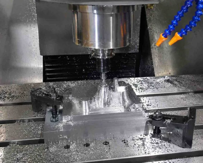
All numerical examples are hypothetical checks of motion or axial space. They are not CNC programs, approved tool selections or measured MW+ production results. The existing library images illustrate machining and component contexts; they do not verify a thread profile, tolerance or customer project.
Contents
Thread milling vs tapping: compare the process mechanisms
Sandvik describes thread milling as a rotating tool generating a thread through circular ramping, requiring coordinated movement in X, Y and Z. [1] The cutter rotates about its own axis while its center follows the programmed path. That distinction matters when reviewing machine capability and the meaning of a programmed revolution.
Cutting taps remove material and generate chips. Forming taps produce the thread without generating cutting chips, but require suitable material ductility, a controlled pre-hole and appropriate lubrication. [3] Our recommendation is to distinguish those two tapping routes explicitly rather than comparing thread milling with an unspecified “tap.”
| Review item | Thread milling | Cutting tap | Forming tap |
|---|---|---|---|
| Thread-generation concept | Rotating cutter follows a helical path. | Cutting tap removes material. | Tap forms the material without cutting chips. |
| Machine/process question | Can the control execute the required coordinated path? | Is the tapping cycle and holding arrangement appropriate? | Are the material, pre-hole and lubrication suitable? |
| Hole question | Does the complete cutter assembly have access? | Are full-form depth, lead-in and chip space resolved? | Are preparation size and depth approved for this tap? |
| Acceptance question | Does the finished feature satisfy the same released drawing and inspection requirements? | ||
Keep the comparison functionally equivalent. A quotation using a shallower thread, different tolerance or changed entry feature is not automatically an alternative manufacturing route for the same requirement. Ask the supplier to identify those differences before comparing price or delivery.
Define the finished thread before selecting a tool
Our recommended input record contains the thread system and governing reference, nominal designation, pitch or lead as applicable, hand, tolerance class, required full-form extent and finished condition. Identify the entry face and location controls separately. Attach the mating-component requirements where they are part of acceptance.
Distinguish what the component must be from how it might be made. A note saying “tap” does not resolve an incomplete thread designation. Conversely, where the drawing or customer specification restricts the process, do not treat that restriction as optional. Ask the design authority to approve a proposed change before manufacture.
The thread mill itself also needs review. Sandvik distinguishes single-row and multi-row concepts and full-profile versus V-profile inserts; their use and preparation requirements differ. [8] Do not assume every cutter can produce every diameter or pitch merely because thread milling offers toolpath flexibility.
For this guide, the selection question is intentionally narrower than a thread-standard comparison. Retain the approved designation and ask which proposed tool and process can produce it. Resolve missing standard or tolerance information with the drawing owner rather than inventing a familiar default.

Separate full thread depth from tool clearance
Blind hole threading needs an axial-space review, not just a nominal depth. Sandvik explains that a tap’s chamfer distributes cutting across several teeth and discusses different chamfer arrangements for different holes. [3] Obtain the actual tool drawing before converting a required full-form endpoint into the deepest tool position.
We recommend marking four items against one reference face: the required last full-form thread location, the tool’s leading extent beyond that location, the usable prepared-hole limit and the required clearance. Add the actual entry feature and bottom shape to the section view. A pointed hole bottom must not silently be treated as a flat usable region.
Hypothetical axial-clearance calculation
Assume positive depth into the part from the entry face. The specified full-form thread endpoint is T = 15.00 ± 0.10 mm. For an invented tool, assume the leading extent below the generating full-form location is A = 3.00 ± 0.10 mm. Assume a flat usable prepared-hole depth D = 22.00 ± 0.20 mm and a separately required minimum bottom clearance B = 2.00 mm.
For this simplified envelope only, define spare margin M = D − T − A − B. Nominally, M = 22.00 − 15.00 − 3.00 − 2.00 = 2.00 mm. At the smallest prepared depth and largest tool requirement, M = 21.80 − 15.10 − 3.10 − 2.00 = 1.60 mm.
| Assumed item | Review value | Role in the simplified envelope |
|---|---|---|
| Usable flat depth D | 22.00 ± 0.20 mm | Use the minimum available depth for the limiting check. |
| Full-form endpoint T | 15.00 ± 0.10 mm | Use the deepest required endpoint. |
| Tool leading extent A | 3.00 ± 0.10 mm | Use the largest assumed tool extension. |
| Required clearance B | 2.00 mm minimum | An invented requirement, not a toolmaker recommendation. |
| Limiting spare margin | 1.60 mm | Available within this ideal axial model only. |
A positive result answers only this axial-envelope question. It does not establish correct minor diameter, sufficient chip space, thread form, entry geometry, cutting conditions or safe machine travel. Position uncertainty, thermal effects and actual bottom shape also remain outside this example.
If the real design cannot accommodate the proposed tool, request a different tool concept or a design review. Do not shorten the required thread or deepen the hole into neighboring geometry without approval. Review the thread mill’s own cutting, neck and leading geometry independently; the invented tap-style envelope is not automatically its clearance model.
Match chip handling and forming conditions to the application
OSG identifies spiral-flute taps for blind holes and spiral-point taps for through-holes in materials producing coiling chips. [4] This is a documented selection distinction, not a rule that every blind hole or material takes the same tool. Ask for the proposed tap’s applicable material and hole guidance.
Sandvik’s tapping recommendations include secure clamping, correct drill and tap selection, drill condition and appropriate fluid delivery. Its discussion connects coolant supply with chip evacuation, thread quality and tool life. [5] Our recommendation is to include those process inputs in the review rather than treating chip removal as an inspection-only cleanup task.
For forming, obtain the selected tap’s preparation requirements. Sandvik identifies material ductility, accurate pre-hole diameter and lubrication as preconditions. [3] Do not transfer a cutting-tap drill size to a forming process without checking the actual tool data and finished-thread limits.
For either cutting route, ask how chips will leave the working region and what cleaning is required before inspection or assembly. Define any relevant cleanliness acceptance rather than assuming that a visible hole opening proves the internal feature is clear. These are recommended review questions, not claims that one process cannot fail.
Check motion, pitch and feed definitions
Haas describes rigid tapping as synchronizing spindle RPM with feedrate. [7] Thread milling is different: Sandvik explains that X–Y motion controls the thread diameter while coordinated axial motion controls the pitch. [2] A cutter spindle revolution and an orbital revolution of the cutter center are therefore different events.
Illustrative single-start motion check
Assume a single-start thread with lead equal to an assumed pitch of 1.50 mm. By the stated geometric model, one revolution along the helix advances 1.50 mm axially. An ideal 12.00 mm axial span corresponds to 12.00/1.50 = eight lead intervals. It does not establish eight usable turns after entry and exit allowances.
For a hypothetical rigid-tapping spindle speed of 800 rev/min, advancing 1.50 mm per revolution gives an ideal synchronized axial feed of 1,200 mm/min. This is unit-checked kinematics, not a recommended speed, tool selection or control command. Follow the actual machine’s units, feed mode, cycle and toolholding documentation.
Do not apply that multiplication to the thread mill’s spindle RPM as though it were a tapping cycle. Sandvik also distinguishes peripheral feed from the tool-center feed required by many controls. [2] Request the toolmaker’s applicable calculations and check what the CAM output and machine actually interpret before proving a program.
Our suggested review record names the tool, control, postprocessor, units, feed definition, entry and exit path, offset convention and verified clearance envelope. Keep this record with the setup revision. The article intentionally supplies no executable program or universal interpolation feed.
Review thread milling advantages without universal claims
Tool flexibility is one reason to evaluate thread milling. Sandvik describes applications in which a multi-row tool serves more than one thread size at the same pitch, and distinguishes that concept from other cutter arrangements. [8] The compatibility must still be checked for the selected profile, diameter, reach and tool guidance.
Thread geometry also limits the selection. Sandvik’s application tips explain that cutter diameter, threading diameter and pitch affect profile deviation. [2] Therefore, a cutter that physically enters the hole is not automatically a qualified cutter for the specified finished form. Ask for the selection rationale and resulting inspection plan.
Compare complete proposals rather than declaring one process always faster or more accurate. Request cycle assumptions, tool changes, preparation operations, inspection and the cost of a rejected component where relevant. A supplier-specific trial can support that comparison; this article provides no cycle-time or cost-saving percentage.
Evaluate tool-failure consequences separately from thread acceptance. Ask what happens if a tool fails, whether inspection or rework is permitted and who authorizes recovery. Do not describe thread milling as damage-proof or tapping as automatic scrap. The disposition of an actual affected component requires evidence and approval.

Verify the finished thread independently of the chosen process
OSG identifies thread-limit plug gauges for female threads and offers long-neck configurations for deep or obstructed locations. [6] Gauge access is therefore a practical planning question. Confirm the specified gauge system, size, tolerance, reach and condition before assuming the feature can be checked as intended.
Our recommended acceptance plan separates thread form and size, usable depth, prepared-hole requirements, entry condition and location relative to the part datums. Identify which characteristic each method checks. Do not turn successful entry of an ordinary mating screw into proof of every drawing requirement.
A gauge’s allowable engagement and rejection rules must come from the applicable specification and agreed inspection procedure. This guide does not prescribe a universal NOT-GO turn count. Where coatings or other treatments follow machining, state which condition is controlled and whether inspection is required at more than one stage.
For the report, request feature identification, drawing revision, gauge or instrument identity, relevant calibration status and the result against each agreed requirement. Record a deviation explicitly if the planned method cannot reach the full controlled region. Do not silently report an accessible portion as acceptance of an inaccessible depth.
Use a process-selection checklist
| Decision | Evidence to request | Question to close |
|---|---|---|
| Finished thread | Approved designation, extent and finished condition. | Are both process proposals addressing the same feature? |
| Hole envelope | Section view and actual tool geometry. | Can full form be produced with the required clearance? |
| Material and preparation | Grade, condition and applicable pre-hole guidance. | Is the proposed cutting or forming route appropriate? |
| Machine and program | Control capability, toolholding and reviewed path. | Are motion and feed definitions understood? |
| Chip handling and cleaning | Proposed process and acceptance requirements. | How will the internal region be cleared and verified? |
| Inspection and changes | Characteristic-specific checks and approval responsibilities. | Who closes a nonconformity or proposed substitution? |
Frequently asked questions
When should I use thread milling instead of tapping?
Evaluate it when the proposed helical path, cutter selection and inspection plan address the application’s constraints. Compare those with a specific tapping proposal, not an unspecified tap. Neither route is selected solely by this guide’s general comparison.
Can one thread mill make every internal thread?
No blanket compatibility is established. Sandvik distinguishes cutter concepts and pitch/profile requirements; actual diameter, reach and profile suitability must be checked. [8] Request approval for the specific tool and thread combination.
Is a forming tap the same as a cutting tap?
No. Cutting taps generate chips; forming taps do not generate cutting chips and need suitable ductility, preparation and lubrication. [3] Keep their pre-hole requirements distinct.
Does blind-hole depth equal full thread depth?
Do not assume equality. The actual tool’s leading geometry and required clearance need space beyond the required full-form endpoint. Our hypothetical envelope illustrates the subtraction but supplies no universal extra-depth allowance.
Does a passing gauge prove joint strength?
The recommended inspection record should state the characteristics actually checked. Separate drawing conformity from an assembly strength or life requirement, and require the responsible engineer’s approved validation when those outcomes are specified.
Prepare the manufacturing enquiry
For mechanical components with internal threads, include the model, controlled drawing, material condition and inspection requirements. Mark any unresolved full-depth, entry or finishing decision before requesting production pricing.
When seeking CNC manufacturing support for the threaded features, ask the supplier to explain its proposed process selection. Use the milling capability overview for relevant process context, then confirm the scope for the actual component.
The MetalWorksPlus company overview provides company context. A useful next step is agreement on the finished feature, feasible tool access and required evidence, with process changes approved before manufacture.
Technical references
- Sandvik Coromant: What Is Thread Milling?.
- Sandvik Coromant: Thread Milling Application Tips.
- Sandvik Coromant: Selecting the Right Tap Type.
- OSG: Taps and Thread Mills.
- Sandvik Coromant: Tapping Operation Tips.
- OSG: Thread Gauges.
- Haas: Mill Rigid Tapping.
- Sandvik Coromant: Choosing Thread Milling Cutters.
References support the identified process descriptions. Supplier-specific guidance is not an MW+ capability guarantee. All examples require application-specific review before use.