






The counterbore vs countersink choice starts with the fastener’s bearing geometry: a counterbore is a cylindrical enlargement with a flat seat, while a countersink is a conical enlargement for a compatible countersunk head. Select the hardware first, then define the recess dimensions and required assembled head position. A shared thread size does not establish an interchangeable head or seat. [1]
This educational guide explains how to turn that distinction into a reviewable drawing and inspection request. It covers fastener-seat features rather than general thread selection, locating-pin fits or a complete bolted-joint strength calculation. All numerical examples are hypothetical geometry exercises, not released designs or MW+ production results.
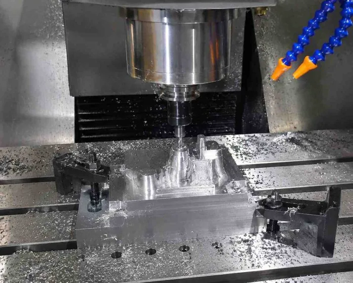
Our practical recommendation is to agree three things before requesting manufacture: the identified fastener, the controlled seat geometry and the evidence needed to confirm the assembled condition. Photographs below are existing library illustrations, not proof that a particular fastener or feature has been validated.
Contents
Counterbore vs countersink: compare the finished geometry
A counterbore hole provides an enlarged cylindrical region around the smaller hole, with a flat-bottomed seating region. A countersink instead enlarges the opening with a cone. The University of Florida fastener handout describes these as cylindrical and conical secondary enlargements, respectively. [1] Distinguish the finished feature from the name of the cutting tool: the drawing must communicate what the assembly needs.
| Review item | Counterbore | Countersink |
|---|---|---|
| Seat geometry | Flat seating region within a cylindrical recess. | Conical seating region. |
| Hardware question | What head, washer and driver envelope must enter? | What head profile and included angle must mate? |
| Recess dimensions | Diameter and depth are separate inputs. | Opening diameter and included angle are separate inputs. |
| Assembly question | Where must the top of the hardware sit? | What head position and contact condition are required? |
| Do not infer | A named recess does not prove joint strength. | A flush-looking head does not prove angle conformity. |
Autodesk’s hole reference treats the smaller hole, counterbore diameter, counterbore depth, countersink diameter and countersink angle as distinct parameters. [2] Use that separation in the review even if the CAD system offers a convenient fastener preset. A preset is a useful starting point; our recommendation is to compare its output with the approved hardware drawing and assembly requirements.
Do not select between the features by an assumed universal cost or strength ranking. For a quotation comparison, ask both proposals to meet the same released assembly requirements and identify any changed hardware or geometry. If the proposals differ functionally, the price comparison alone does not answer the engineering question.
Define the actual fastener and assembled condition
Begin with a controlled hardware record: part number, applicable specification, head form, relevant dimension limits and approved revision. Include any washer or other item intended inside the recess. State whether the final top surface must be flush, recessed within a range or simply clear of a neighboring part.
A manufacturer’s data illustrates why identity matters. Accu lists a 90-degree countersunk angle with a +2/−0-degree tolerance for its SSK-M8-90-A2 product. [3] That is a specific product’s published specification, not a tolerance to copy automatically onto the mating seat or every metric fastener. Obtain the actual screw drawing and determine which mating requirements the design authority approves.
In particular, do not confuse the included angle across the cone with the half-angle used in a section calculation. A nominal 90-degree cone has a 45-degree half-angle by geometry. Our recommendation is to use the drawing system’s unambiguous angle notation and label any calculation variables explicitly.
For a counterbore, review the full installation envelope rather than only the visible head. Ask whether the intended washer fits, whether the driver can reach its working position and whether adjacent geometry obstructs removal. These are assembly-review questions; there is no universal extra diameter prescribed here.
For either feature, identify the specified assembly state. Is acceptance checked before or after finishing? Is head position evaluated with the production hardware and approved assembly procedure? Record the responsible owner when torque, preload or structural verification lies outside the machined-component supplier’s scope. Do not turn this dimensional guide into an unsupported tightening specification.

Specify fastener seats on the drawing
The fastener handout separates the smaller hole from its enlargement and describes counterbore diameter/depth and countersink angle/opening requirements. [1] ASME’s public Y14.5 description establishes the broader scope of drawing symbols and requirements; this article does not reproduce inaccessible clauses or prescribe one universal callout. [6]
Our recommended drawing review starts with the entry side and smaller hole. Identify the correct face, nominal geometry, size limits and extent. Then check the enlarged feature independently. A depth attached to the wrong portion of a hole can leave two reviewers discussing different surfaces even when they agree on the number.
For the counterbore, identify the recess diameter and the reference surface for depth. Review the flat seating region and any permitted corner transition against the actual head or washer geometry. If a local bearing land is required, describe its acceptance requirements rather than relying on the word “flat” without an agreed meaning.
For the countersink, identify the opening diameter and included angle, with applicable tolerances. State the functional head-position requirement where necessary and agree how it relates to the geometric limits. Do not add redundant independently toleranced dimensions without checking whether they can all be satisfied together.
Also identify quantity, pattern location, relevant datum relationships and the required finished state. The seat-size question is separate from the hole-pattern question. Where a drawing needs geometric controls, use the specified standard and approved design interpretation; do not assume that a recess automatically locates the entire assembly.
A useful review note should expose unresolved decisions. For example: “Confirm opening-size limits and assembled head position against the selected fastener drawing.” That is more actionable than “countersink to suit,” but it remains a review instruction until the missing requirements are approved and released.
Check depth and tolerance with explicit geometry
Example 1: a hypothetical conical enlargement
Assume an ideal coaxial cone joins a cylindrical hole of diameter d to an opening of diameter D, with included angle θ. Let t be the axial distance between those two circular sections. In an axial section, the radial increase is (D − d)/2. Basic right-triangle geometry gives t = (D − d) / [2 tan(θ/2)].
This is an original geometric derivation for that ideal shape. It does not model the screw’s complete head, truncation, under-head transition, deformation or actual bearing contact. Use consistent diameter units and the correct angle mode in the calculator. Do not mistake t for a purchased screw’s tabulated overall head height.
Choose hypothetical values D = 12.00 mm and d = 6.00 mm. At θ = 90 degrees, tan(45 degrees) = 1, so t = 3.00 mm. At an assumed θ = 82 degrees, t is approximately 3.451 mm. The two angles are comparison inputs, not an approved fastener pairing.
| Assumed cone | Calculation | Ideal axial distance |
|---|---|---|
| D = 12.00 mm; d = 6.00 mm; θ = 90° | 6.00 / [2 tan(45°)] | 3.000 mm |
| Same diameters; θ = 82° | 6.00 / [2 tan(41°)] | Approximately 3.451 mm |
| θ = 90°; D increases by 0.10 mm; d unchanged | Δt = 0.10 / 2 | Axial distance increases by 0.050 mm |
The consequence is limited but useful: changing angle while holding the two diameters fixed changes the ideal axial distance. It does not prove that a mismatched screw will make acceptable contact. Review the actual mating profiles and approved inspection method before using the model in a design decision.
Example 2: nominal counterbore depth can hide a proud head
Assume a hypothetical flat stack comprising a head height of 3.00 ± 0.05 mm and washer thickness of 0.50 ± 0.03 mm. Assume the counterbore floor is 3.60 ± 0.05 mm below the reference face. Define recess margin M as depth minus the head-and-washer stack. Positive M means the ideal stack top is below the face; negative M means it projects above it.
Nominally, M = 3.60 − 3.00 − 0.50 = +0.10 mm. At the smallest depth and largest stack, M = 3.55 − 3.05 − 0.53 = −0.03 mm. At the opposite limits, M = 3.65 − 2.95 − 0.47 = +0.23 mm. The assumed limits therefore permit a proud condition despite a recessed nominal result.
This worst-case subtraction assumes ideal parallel flat surfaces and an additive rigid stack. It omits coatings, seating transitions, deformation, form error and measurement uncertainty. It establishes a dimensional risk to resolve, not an acceptable joint. Our recommendation is to review the actual hardware limits and required head-position band rather than increase depth without checking the remaining component geometry.
Plan machining and inspection together
A flat-bottomed requirement needs a process capable of producing the specified seat. Harvey Performance discusses flat-bottom counterbores and the distinction between removing a drill-point profile and removing the dish left by some end-mill operations. [5] This supports asking about the resulting surface, not assuming that any operation named “bore” establishes the required floor.
For process review, provide the material condition, entry face, surrounding features and critical seat requirements. Invite a proposed operation sequence and identify which characteristics require final verification. The supplier should confirm the actual scope; this guide does not claim MW+ uses any particular cutter, inspection instrument or cycle for an unquoted part.
For a countersink, agree how size and angle will be assessed. Starrett describes angle-matched countersink gages that contact the angular side, contrasting them with chamfer gages that contact the top edge. [4] That distinction makes gage selection a real review item. It does not establish that any single reading verifies every characteristic of the seat.
Our recommended inspection plan lists opening diameter, included angle, seat depth where controlled, location and functional head position separately. Select methods with suitable access and agreed measurement capability. Record the reference surface, part state and decision rule so that results can be interpreted against the released requirement.
For a counterbore, separate recess diameter from depth and the required bearing-surface condition. For both types, inspect the smaller hole and pattern as required by the drawing. A satisfactory check of the visible enlargement should not silently become acceptance of unmeasured features.
Keep the trial-assembly record distinct from the dimensional report. If an approved assembly check is required, identify the hardware and procedure used. A photograph of a flush screw can support documentation of that trial, but our recommendation is not to use it as a substitute for the specified geometric measurements or joint validation.

Use a feature-specific release checklist
| Release item | Recommended record | Question to close |
|---|---|---|
| Hardware | Part number, drawing and approved alternatives. | Which head and additional stack items must fit? |
| Seat definition | Entry side, geometry, limits and reference face. | Are diameter, angle and depth unambiguous? |
| Assembly envelope | Head position, driver and removal requirements. | Can the approved assembly be installed and serviced? |
| Component geometry | Remaining material and adjacent-feature review. | Has the design owner accepted the complete shape? |
| Finished state | Processing stage and coating requirements. | When must the dimensions meet their limits? |
| Inspection | Method, reference setup and reporting plan. | Which evidence closes each characteristic? |
| Changes | Approved revision and scope exclusions. | Who authorizes a proposed geometry substitution? |
Use the checklist to prevent an unresolved item from disappearing between design, purchasing and manufacture. Assign an owner and a release decision for each open question. When a supplier proposes a change, compare it with the same functional requirement rather than approving a different seat merely because it is easier to machine.
Frequently asked questions
Can a counterbore and countersink be interchanged?
Not as an automatic substitution. Their seating shapes differ. Review the chosen hardware, finished geometry and assembly requirements before approving a change; retaining the same thread size does not resolve those questions. [1]
Is every metric countersink exactly 90 degrees?
Do not use that assumption as a drawing requirement. The cited Accu product lists a nominal 90-degree angle with a stated tolerance. Use the actual fastener specification and approved mating requirements rather than applying one product’s values universally. [3]
Does a countersink diameter measurement also verify angle?
Our recommendation is to treat diameter and angle as separate required characteristics. Starrett’s description shows why the selected gage angle and contact location matter. Agree the verification method for each controlled requirement instead of assigning additional meaning to one reading. [4]
How deep should a counterbore be?
Determine it from the actual hardware envelope and required head position, then review the permitted limits and remaining geometry. The hypothetical stack above demonstrates why a recessed nominal result does not guarantee a recessed worst-case condition. It supplies no standard depth for a screw size.
Does either seat guarantee a stronger or cheaper joint?
This article establishes no universal strength or cost ranking. Request an application-specific engineering assessment and a quotation against the released design. Do not treat the recess name as evidence of preload, vibration resistance, service life or manufacturing cost.
Prepare a useful machining enquiry
For machined mechanical parts with fastener seats, send the component model, controlled drawing, selected fastener data and assembled head-position requirement together. Mark unresolved seat or hardware decisions before asking for production pricing.
When requesting CNC machining support for the specified seat features, include the finished state and inspection expectations. Where the component calls for a milling review, the MW+ milling service overview provides the relevant process context; the proposed route still needs confirmation for the actual drawing.
The MetalWorksPlus company overview provides broader company context. A useful next step is an agreed feature-and-evidence package: what will be manufactured, what will be measured and which assembly questions remain with the design owner.
Technical references
- University of Florida Design Lab: Fastener Handout.
- Autodesk Fusion: Hole reference.
- Accu: SSK-M8-90-A2 socket countersunk screw.
- Starrett: Countersink Gages.
- Harvey Performance: 10 Reasons to Use Flat Bottom Tools.
- ASME: Y14.5 Dimensioning and Tolerancing.
References support the identified technical descriptions. The University of Florida handout is an educational source, not a substitute for the governing drawing standard. All worked inputs and calculations are illustrative and require application-specific review before use.