







Heat sink fin design should begin with the allowable temperature rise and the actual cooling environment, then reconcile fin spacing, fin height, base geometry and machining access. Adding fins increases geometric area, but it does not establish better cooling if the resulting channels restrict the available airflow. Boyd’s selection guidance and Advanced Thermal Solutions’ spacing discussion explain why the operating conditions belong in the design decision. [1] [2]
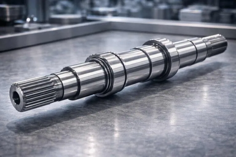
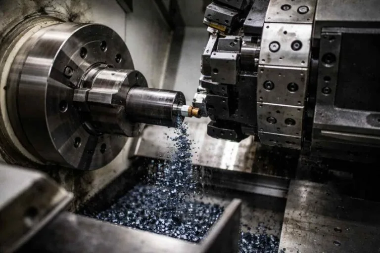
Application-guide disclosure: this is an illustrative engineering study, not an MW+ customer project. All example temperatures, resistances and dimensions are assumed teaching inputs. No simulation, temperature test, production result or validated cooling capacity is claimed. Existing library images illustrate component and manufacturing contexts, not the example geometry.
The objective is a reviewable design package: a thermal requirement, candidate geometry, a proposed manufacturing route and separate dimensional and thermal acceptance plans. The recommendations below help organize that package; the responsible engineers must approve the real inputs and validation criteria.
Contents
Establish the thermal budget before heat sink fin design
In a simplified steady-state thermal circuit, thermal resistance is temperature difference divided by heat flow, expressed in °C/W or K/W. Boyd describes a serial junction-to-case, case-to-sink and sink-to-air model. Under that model, the available sink-to-air resistance is the total allowable temperature-rise budget divided by power, minus the upstream resistances. [1]
Use the model only when its assumptions fit the application. For this teaching example, assume all dissipated power follows that single path, each resistance represents the defined operating state, and transient storage and parallel heat paths are neglected. The example does not determine whether a real package’s quoted junction-to-case value is appropriate for an installed assembly.
Worked thermal-resistance budget
Assume maximum junction temperature Tj,limit = 100 °C, local cooling-air reference Ta = 40 °C, dissipated power Q = 30 W, junction-to-case resistance Rjc = 0.30 K/W and case-to-sink resistance Rcs = 0.20 K/W. These values are invented inputs, not a device datasheet or recommended operating limits.
The allowable total resistance is (100 − 40)/30 = 2.00 K/W. Subtracting 0.30 and 0.20 leaves Rsa,max = 1.50 K/W. Checking backwards gives 40 + 30 × (0.30 + 0.20 + 1.50) = 100 °C. The units are consistent: watts multiplied by kelvins per watt give a temperature difference.
If a hypothetical candidate instead had Rsa = 1.80 K/W at the same defined condition, the model would give 40 + 30 × 2.30 = 109 °C, above the assumed limit. This is arithmetic on assumed resistances, not a prediction for either fin layout below. Meeting the 1.50 K/W boundary would also leave no additional allowance within this deliberately simplified budget.
Our recommendation is to list uncertainty and required design allowance explicitly, rather than hide them in optimistic inputs. Obtain the actual device limits, applicable package thermal guidance, power profile and interface evidence before accepting a numerical target. Keep the heat-source footprint and temperature reference locations in the review record.
Choose fin spacing for the cooling environment
Natural convection relies on buoyancy, while forced convection uses externally driven airflow. Boyd emphasizes that heat-sink resistance depends on external cooling conditions. [1] Consequently, our recommended review begins by recording installation orientation, the air reference location, surrounding obstructions and whether the assembly uses a fan, blower or no powered air mover.
Fin spacing means the clear channel between adjacent fins, rather than the center-to-center pitch. ATS notes that overly narrow channels obstruct airflow in natural-convection cooling. [2] Do not copy one gap from a photograph or a different product and call it optimal. Ask the thermal reviewer to compare candidates under the intended orientation and enclosure conditions.
For forced airflow, review the fan and system together. Oriental Motor explains that actual flow and pressure occur at the intersection of the fan performance curve and system-impedance curve; maximum airflow and maximum static pressure are different endpoints. [3] A free-air airflow number therefore does not establish the flow through this fin field.
ATS also describes how dense, unducted fin arrays can increase pressure drop and divert flow around the heat sink. Its selection methodology distinguishes fin efficiency and heat-transfer coefficient from simple surface area. [8] Our recommendation is to document the intended duct, shroud, bypass gaps, inlet and outlet when comparing layouts.
| Design situation | Review emphasis | Evidence to request |
|---|---|---|
| Buoyancy-driven cooling | Channel openness and installed orientation. | Analysis or testing in the defined enclosure and orientation. |
| Fan-driven cooling | Delivered flow, pressure loss and bypass. | Applicable fan curve and system operating-point assessment. |
| Changed fin count | Area gain alongside channel-width change. | Side-by-side geometry and thermal comparison under common conditions. |
| Changed installation | Whether the previous result still applies. | Review of changed boundaries before reusing the rating. |

Compare two hypothetical fin layouts
Consider an ideal straight-fin field spanning W = 60.00 mm across its width. Each fin has thickness t = 1.50 mm, exposed height H = 20.00 mm and length L = 50.00 mm. Assume the two outer fins finish exactly at the field boundaries, with no outside margins, taper, root transitions or interruptions. There are N fins and N − 1 equal internal gaps.
Under these assumptions, s = (W − Nt)/(N − 1), where s is clear spacing. This is original dimensional bookkeeping: fin thicknesses and gaps must sum to the defined field width. It is not a thermal correlation or toolmaker recommendation.
Thirteen fins versus seventeen fins
| Assumed layout | Clear-gap calculation | Gap | Two large faces per fin |
|---|---|---|---|
| 13 fins | (60.00 − 13 × 1.50)/12 | 3.375 mm | 2 × 13 × 20 × 50 = 26,000 mm² |
| 17 fins | (60.00 − 17 × 1.50)/16 | 2.15625 mm | 2 × 17 × 20 × 50 = 34,000 mm² |
The denser layout has approximately 30.8% more area on the two large faces of its fins: (34,000 − 26,000)/26,000 × 100. At the same time, clear spacing falls by 1.21875 mm. Neither result calculates pressure drop, local velocity, fin efficiency or temperature. The area subtotal excludes fin tips, ends, exposed base and any root geometry.
This comparison exposes a tradeoff rather than choosing a winner. As ATS explains, nominal area alone does not determine the convection resistance when flow and fin effectiveness also change. [8] Ask for a thermal comparison using the real boundaries before accepting the denser design.
For a machining review, provide both layouts rather than labeling one “easy.” Ask the supplier to identify an actual tool assembly, access route and inspection approach for each. A cutter diameter smaller than the nominal gap would be only one geometric check; it would not establish suitable reach, holder clearance, chip removal or a stable cutting process.
Retain tolerance information in the next revision. This exact-geometry calculation does not include fin-thickness or position variation. We recommend asking which local minimum gap must remain available, how thickness and location are controlled, and where measurements will be taken. Avoid using the average gap as the sole acceptance requirement when the function depends on individual channels.
Review the base, interface and material together
The base distributes heat from the source into the fin field. ATS discusses spreading resistance when the heat-source footprint is smaller than the base. It also explains a constrained-height tradeoff: a thicker base can improve spreading while leaving less height for fins. [4] Its particular example does not supply a universal optimum thickness for another design.
Our recommendation is to compare candidate base thicknesses within the actual total-height limit. Mark the source footprint, attachment locations and available fin height together. Request the analysis assumptions and explain why the chosen geometry is acceptable; do not release a thickness solely because it appears in another supplier’s guide.
The case-to-sink interface is another distinct part of the thermal path. Boyd identifies surface condition, flatness, contact area, mounting pressure and interface-material thickness among the relevant inputs. [1] For release, request the approved interface product and assembly requirements rather than treating a generic pad description as a measured resistance.
Aluminum and copper are common heat-sink materials, but material selection also affects mass and manufacturing considerations. Protolabs discusses those tradeoffs and identifies CNC machining among the available routes. [6] For an aluminum heat sink design, specify the exact grade, temper and relevant property source. This article assigns no pure-metal conductivity value to an unspecified alloy.
Keep this application review distinct from a broad alloy-selection exercise. Our 6061 and 7075 comparison covers that separate question. Here, the required output is an approved material record and thermal model using applicable properties, without claiming that alloy strength alone selects the best fin geometry.
Make the fin field reviewable for machining
First identify the intended construction. Boyd’s fabrication guide distinguishes extruded profiles with secondary machining, skived fins and bonded-fin assemblies. [7] Their geometry and process descriptions are not interchangeable manufacturing limits. This study considers a proposed machined component; it does not assert that MW+ offers every heat-sink construction.
When discussing milling access for the fin field and base, provide the complete model and drawing. Ask the supplier to identify the proposed blank, operation sequence, tool-entry direction, accessible channel depth and permitted corner transitions. Request clarification of any change needed before accepting it into the released design.
Review cutter stability and fin support
Sandvik Coromant’s shoulder-milling guidance treats thin-wall strategy as dependent on wall height and thickness, and calls for considering both cutter and wall stability. It also discusses short tool overhang and staged approaches that retain support during machining. [5] Those principles justify a process review; they do not certify a particular fin thickness or universal height-to-thickness ratio.
We recommend asking how the proposed sequence preserves the base reference and supports the developing fins. Record whether temporary stock, alternative access or a changed sequence is proposed. Ask how burrs and remaining material inside the channels will be addressed without silently changing the approved fin profile.
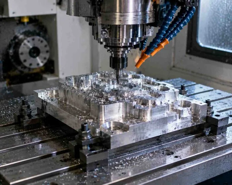
Separate functional requirements from cosmetic expectations. Identify the heat-transfer contact face, mounting datums, critical channel dimensions and exposed handling edges. Apply specific acceptance criteria where the assembly needs them, and ask the supplier to flag requirements it cannot verify. Do not infer thermal performance from a uniformly bright machined appearance.
Separate dimensional inspection from thermal validation
Our recommended dimensional plan identifies field width, fin thickness, local gaps, fin height, overall height, base thickness and mounting features. State reference surfaces and measurement locations. If a channel cannot be reached by the proposed instrument, resolve that access question before relying on its report.
For the interface face, define the approved form and surface requirements and whether they apply before or after finishing. Request a part-state record and an inspection method appropriate to the specified characteristic. A photograph can illustrate the part, but it does not replace the agreed dimensional evidence.
Then create a separate thermal-validation plan. Define the applied power, reference temperatures, sensor locations, mounting and interface procedure, orientation and airflow configuration. Agree the stabilization criterion and acceptance rule before testing. These are proposed review items, not a claim that any test has been performed.
Match the validation to the released configuration. If the prototype uses a different interface, fan, shroud or orientation, document that difference and ask the thermal owner whether the result remains applicable. Preserve the raw observations alongside calculated resistance so a reviewer can reproduce the reported calculation.
Use a release checklist
| Release item | Recommended record | Unresolved issue to close |
|---|---|---|
| Thermal requirement | Power profile, temperature limits and approved budget. | Are inputs applicable to the actual device and assembly? |
| Cooling environment | Orientation, air reference and fan/system assessment if used. | What flow actually reaches the fin channels? |
| Candidate geometry | Fin count, thickness, spacing, height, length and base definition. | Do tolerances preserve the intended local geometry? |
| Material and interface | Exact material condition, interface product and assembly requirements. | What evidence supports the model inputs? |
| Manufacturing | Reviewed access, support sequence and finishing scope. | Has the supplier accepted the complete drawing? |
| Acceptance | Separate dimensional report and thermal-validation plan. | Who approves each result and outstanding deviation? |
Frequently asked questions
What is the best heat sink fin spacing?
There is no single gap selected by this guide. Review the cooling mode, orientation, airflow path and geometry together. ATS explains why narrow channels can obstruct natural-convection airflow; the actual spacing still needs application-specific evaluation. [2]
Do more fins always mean better cooling?
No. The worked example proves an area increase and a gap reduction only. ATS’s selection methodology explains that fin effectiveness, flow resistance and bypass matter as well. Use thermal evidence under common conditions to compare candidates. [8]
How thin can a machined heat sink fin be?
This guide gives no universal minimum. Sandvik’s thin-wall guidance links the strategy to wall dimensions and stability. [5] Request a supplier review of the actual material, fin geometry, tool access and acceptance requirements.
Does a larger base always solve the thermal problem?
No universal conclusion follows. Under a fixed height envelope, ATS describes a tradeoff between spreading through the base and the remaining fin height. [4] Review the complete geometry rather than maximizing one dimension independently.
Does the 1.50 K/W example rate the illustrated heat sink?
No. It is a calculated budget using explicitly assumed inputs. The photographs have no associated thermal test record here. Neither pictured component is identified as either hypothetical fin layout.
Prepare the manufacturing enquiry
For precision components with fins and mounting interfaces, include the released drawing, CAD model, exact material condition and inspection requirements. Attach the thermal boundary conditions as engineering context and identify any geometry still awaiting approval.
Discuss the proposed manufacturing scope through CNC machining services for the reviewed component, while assigning thermal analysis and assembly validation explicitly. Ask for a process proposal tied to the actual drawing rather than an assumed cooling result.
The MetalWorksPlus company overview provides company context for the enquiry. The useful next step is agreement on manufacturable geometry and the evidence each party will supply, with open thermal and dimensional questions recorded before release.
Technical references
- Boyd: How to Select a Heat Sink.
- Advanced Thermal Solutions: Heat Sink Fin Spacing in Natural Convection.
- Oriental Motor: Fan Basics, Air Flow, Static Pressure and Impedance.
- Advanced Thermal Solutions: Optimizing Heat Sink Base Spreading Resistance.
- Sandvik Coromant: Shoulder Milling.
- Protolabs: Materials for Heat Sinks.
- Boyd: Heat Sink Fabrications Guide.
- Advanced Thermal Solutions: Heat Sink Selection Methodology.