A ±0.001mm tolerance band is not a programming setting. It is a set of physical conditions the shop floor has to hold — temperature, clamping force, tool engagement, measurement traceability — and any one of them going unmanaged is enough to lose the tolerance regardless of how good the machine is.
This page covers what a machine shop must actually do to hold ±0.001mm: thermal control, workholding, cutting strategy, metrology and material stability. It is written for the engineer deciding whether to put that number on a drawing, and for the buyer trying to work out whether a supplier claiming it can support the claim.
Key takeaways
- Thermal control comes first. Aluminum 6061-T6 has a nominal coefficient of thermal expansion near 23.6 µm/m·K, so a 100mm dimension grows about 2.4 µm for every 1°C — more than twice a ±0.001mm band, from one degree.
- ±0.001mm is a feature-level specification, not a drawing-level one. MW+ holds general machining to ±0.01mm against ISO 2768-m, precision features to ±0.005mm, and a floor of ±0.001mm on suitable geometry and material.
- The measurement has to be defensible before the tolerance means anything. A gauge resolving 0.001mm cannot verify a 0.001mm band; the instrument’s own uncertainty must be a small fraction of the tolerance, traceable through a calibration chain.
- Workholding is the most common failure. Clamping force distorts the part, machining removes the stress that balanced it, and the feature moves after release — the dimension is correct in the fixture and wrong on the bench.
- Repeatability, not a single measured part, is what counts in production. Ask for process capability of Cpk ≥1.67 on the nominated characteristic rather than a first-article number.
- ±0.001mm is the wrong specification on thin-walled parts, on non-stress-relieved stock, on features that will be plated afterwards, and anywhere the assembly can be designed to absorb variation instead.
- What does it actually take to hold ±0.001mm?
- Why thermal control is the first requirement, not the last
- What workholding does a sub-micron tolerance part need?
- Tooling, cutting strategy and minimum chip thickness
- How is ±0.001mm actually measured and verified?
- Which materials can realistically hold ±0.001mm?
- What your drawing must say for ±0.001mm to be quotable
- When ±0.001mm is the wrong specification
- How to check a supplier’s sub-micron claim
- Frequently asked questions
What does it actually take to hold ±0.001mm?
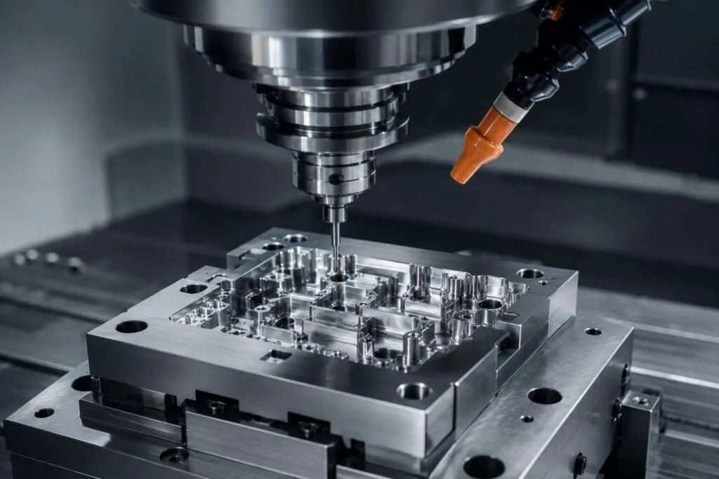
Holding ±0.001mm requires four conditions held simultaneously: a stable temperature at the part and the machine, workholding that does not distort the workpiece, a cutting strategy whose depth of cut stays above the tool’s minimum chip thickness, and measurement whose uncertainty is a small fraction of the tolerance band. Losing any one of the four loses the tolerance, and a capable machine does not compensate for the other three. What the specification itself means, as distinct from what it takes to hold it, is covered in our note on 0.001 mm machining accuracy.
| Tolerance band (mm) | What the shop floor must control | Typical application | Relative cost impact |
|---|---|---|---|
| ±0.1 to ±0.3 (ISO 2768-m general) | Nothing beyond normal practice | Clearance holes, covers, non-mating features | Baseline |
| ±0.01 (general machining at MW+) | Tool wear monitoring, sound fixturing | Housings, plates, general mechanical assemblies | Low |
| ±0.005 (precision) | Separate finishing pass, in-process gauging, controlled shop temperature | Bearing seats, shaft fits, sealing faces | Moderate |
| ±0.001 (sub-micron band) | Temperature-controlled machining and metrology, low-distortion workholding, stress-relieved stock, traceable gauging | Optical mounts, instrument spindles, fluidic and medical instrument features | High; applied per feature, never drawing-wide |
Why thermal control is the first requirement, not the last
Thermal expansion is the largest single error source at ±0.001mm because metals move more per degree than the whole tolerance band is wide. Aluminum 6061-T6 has a nominal coefficient of thermal expansion of about 23.6 µm/m·K, so a 100mm feature grows roughly 2.4 µm per 1°C. A shop that cannot state the temperature its parts were cut and measured at cannot honestly quote the tolerance.
The values below are nominal published figures for common grades. Use them to size the problem, and work from the actual mill certificate when a property is load-bearing in your design.
| Material | Nominal CTE (µm/m·K) | Growth on a 100mm dimension per 1°C (µm) | Implication at ±0.001mm |
|---|---|---|---|
| Aluminum 6061-T6 | ≈23.6 | ≈2.4 | One degree exceeds the whole 2 µm band |
| Stainless steel 304 | ≈17.3 | ≈1.7 | One degree consumes most of the band |
| Stainless steel 316L | ≈16.0 | ≈1.6 | One degree consumes most of the band |
| Titanium Ti-6Al-4V | ≈8.6 | ≈0.9 | Tolerant of ~1°C drift; poor thermal conductivity moves heat into the tool instead |
| Invar 36 | ≈1.2 | ≈0.1 | Chosen specifically when dimensional stability over temperature is the requirement |
Two practical consequences follow. Parts must soak to the metrology room temperature before inspection, typically for hours rather than minutes on a substantial mass. And the inspection temperature has to be recorded, because a measurement without a temperature is not comparable to anyone else’s measurement of the same feature. Nominal property values for these grades are published by sources such as MatWeb, with the underlying material specifications from ASTM International.
What workholding does a sub-micron tolerance part need?
Sub-micron workholding must locate the part repeatably while applying the least clamping force that will resist the cutting load. The failure mode is specific: clamping deforms the workpiece elastically, the machine cuts a feature that is true in the deformed state, and the part springs back when the clamps release. The dimension was correct in the fixture and is wrong on the inspection bench.
Residual stress compounds this. Bar and plate stock carries internal stress from rolling, drawing and heat treatment. Removing material unbalances that stress and the part moves — sometimes over hours. On sub-micron work this is managed by rough machining, stress relieving, then finishing, which costs a process step and a day but is often the only route to a stable dimension.
| Workholding method | Best suited to | Distortion risk at ±0.001mm |
|---|---|---|
| Vacuum chuck | Flat, thin plates and optical substrates | Low clamping distortion; the part can bow if the underside is not flat |
| Precision vise with soft jaws | Prismatic bodies with parallel faces | Moderate; jaw pressure squeezes the part, so force must be set, not guessed |
| Collet chuck | Round stock and shafts | Low if the collet matches the diameter; high if it is undersized and grips on three lines |
| Custom fixture with kinematic location | Repeat production of one geometry | Lowest, and repeatable across a batch; the cost is the fixture |
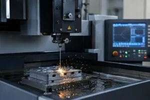
Where the geometry cannot survive any clamping force at all, the answer is usually to change process rather than fixture. Sinker EDM and wire EDM services remove material by spark erosion with no cutting force, which is why they are the standard route for thin webs and sharp internal corners in hardened material.
Tooling, cutting strategy and minimum chip thickness
Every cutting edge has a minimum chip thickness below which it stops cutting and starts ploughing — rubbing the surface, generating heat and deflecting instead of removing material. Finishing passes at sub-micron tolerances have to stay above that threshold, which is set by the edge radius of the tool, not by the machine’s positioning resolution.
Why a smaller finishing cut is not automatically a more accurate one
A common instinct is to take an ever-lighter final pass. Below the minimum chip thickness this makes the result worse: the tool rubs, local temperature rises, the edge wears faster and the surface work-hardens. The correct approach is a defined finishing depth that the edge can cut cleanly, with a sharp tool and a controlled number of parts per edge.
Tool wear becomes a dimensional variable
At ±0.01mm, tool wear across a batch is usually absorbed by the tolerance. At ±0.001mm it is not. A shop holding sub-micron bands runs tools to a counted part limit rather than to visible wear, and offsets from in-process measurement rather than from a nominal tool length. This is one of the clearest questions to ask a supplier: how many parts per edge, and what triggers a change.
Feature size also decides the process. Below roughly 1mm, tooling, spindle speed and metrology all have to be scaled to the feature, which is the domain of micro machining services rather than conventional milling. Slender turned parts hold concentricity better under Swiss machining, because the guide bushing supports the bar at the point of cut instead of some distance behind it.
How is ±0.001mm actually measured and verified?
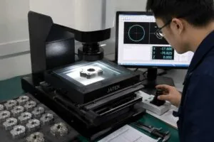
Verifying a ±0.001mm feature requires an instrument whose measurement uncertainty is a small fraction of the 2 µm band, operated in a temperature-controlled room on a part that has soaked to that temperature, with calibration traceable to a national metrology institute. A gauge that displays 0.001mm resolution does not qualify; display resolution and measurement uncertainty are different quantities.
Traceability is the part buyers most often skip. A measurement is only meaningful if the instrument’s calibration chain leads back to a recognised standard; the principle and the calibration services behind it are described by NIST. Ask for the calibration certificate, not the instrument brand. How a coordinate measuring machine produces that evidence is walked through in our guide to the CMM inspection process.
Worked example: what Cpk ≥1.67 means inside a ±0.001mm band
Process capability turns the tolerance into a number the shop floor has to hit. For a centred process, Cpk = (USL – mean) ÷ 3σ, as set out in the NIST/SEMATECH engineering statistics handbook. Work it backwards from the ±0.001mm floor.
Step 1. Set the limits: LSL = -0.001mm, USL = +0.001mm, a total band of 0.002mm, or 2 µm. Step 2. Write the requirement: 1.67 = 0.001 ÷ 3σ. Step 3. Solve for the standard deviation: σ = 0.001 ÷ (3 × 1.67) = 0.0002mm, or 0.2 µm.
Step 4. Convert that to the natural process spread: 6σ = 1.2 µm. The whole run has to fit inside 1.2 µm of a 2 µm band, which leaves 0.8 µm for everything the equation assumes away: centring drift, thermal drift and the uncertainty of the measurement itself, combined.
Step 5. Sanity-check that remainder against the thermal figure above. A 100mm aluminum feature moves about 2.4 µm per 1°C, so 0.8 µm is consumed by roughly 0.33°C of drift. That line is the arithmetic behind a temperature-controlled machining and metrology area, and it is why a supplier who cannot state a shop temperature cannot support the tolerance.
| Measurement task | Typical instrument | What it proves | What it cannot prove |
|---|---|---|---|
| Size of a bore or shaft | Air gauge or bore gauge, mastered to a ring or setting standard | Diameter against a known master, quickly and repeatably | Form errors between the contact points |
| Position and profile of features | Coordinate measuring machine (CMM) | True position, profile and datum relationships per ISO 1101 | Fine surface texture; probe contact force can deflect thin features |
| Surface texture | Contact profilometer or optical profiler, parameters per ISO 21920-2 or the superseded ISO 4287 | Ra, Rz and the finishing process actually used | Dimensional size or position |
| Batch repeatability | Statistical process control against the nominated characteristic | Whether the process is capable, e.g. Cpk ≥1.67 | Nothing about a part not sampled |
Every MW+ order ships with a certificate of conformance, a CMM inspection report and material certificates. First article inspection to AS9102 and PPAP Level 3 submissions are available on request and quoted per programme, and the wider system is described under CNC machining quality control.
Which materials can realistically hold ±0.001mm?
The materials that hold ±0.001mm reliably are those that are dimensionally stable after machining: stress-relieved tool steels, hardened and ground steels, Invar 36 where thermal stability is the requirement, and stabilised aluminum plate such as cast tooling plate rather than as-rolled bar. Free-machining grades cut beautifully and then move, which is why they are a poor choice for a sub-micron feature.
Two material properties matter more than machinability ratings at this level. The first is residual stress state, which decides whether the part is the same shape tomorrow. The second is thermal conductivity, which decides whether heat generated at the cut leaves through the chip or accumulates in the workpiece — the reason titanium alloys such as Ti-6Al-4V are harder to hold to tight bands than their expansion coefficient alone suggests.
MW+ machines 70+ material grades. Specify the full designation and condition on the drawing — Aluminum 6061-T651 rather than “aluminum”, Ti-6Al-4V rather than “titanium” — because the temper and heat treatment change achievable tolerance more than the base metal name does. The range routinely run is set out under CNC machining capabilities.
What your drawing must say for ±0.001mm to be quotable
A quotable sub-micron drawing states five things: which individual features carry the tight band, the datum scheme those features are measured from, the material grade and condition, the surface texture requirement with its Ra value, and the inspection evidence required. A drawing that applies ±0.001mm globally is not a specification; it is a request for the highest possible price.
- Datums before tolerances. A tight size means little without stating what it is measured from. Use a defined datum scheme per ISO 1101 or ASME Y14.5.
- Use a fit class where a fit is what you mean. For a mating bore and shaft, an ISO 286 fit designation such as H7/g6 communicates the functional requirement better than two independent tight bands. The standard is ISO 286.
- Set the general tolerance note explicitly. ISO 2768-m as the default note, with three or four individually tightened dimensions, quotes faster and manufactures cheaper than a blanket tight note.
- State surface texture separately. Dimensional tolerance and surface finish are independent requirements. MW+ produces Ra 3.2µm as-machined, Ra 0.4µm fine-machined and Ra 0.1µm polished. Texture parameters were defined in ISO 4287:1997, superseded by ISO 21920-2:2021; both conventions remain in circulation, so the drawing must state which one governs.
- Say what happens after machining. Anodising, plating and heat treatment all change dimensions. A ±0.001mm feature that is then plated needs the tolerance stated at the correct point in the process.
When ±0.001mm is the wrong specification
±0.001mm is the wrong specification in five common situations: on thin-walled or low-stiffness geometry that will not hold shape, on stock that has not been stress relieved, on features that receive plating or anodising afterwards, on large dimensions where thermal drift alone exceeds the band, and anywhere the assembly can absorb the variation through a shim, a spring or an adjustable mount.
| Situation | Better specification | Why ±0.001mm fails here |
|---|---|---|
| Thin wall or long unsupported section | ±0.01mm plus a flatness or straightness control | The part deflects under clamping and cutting load; form, not size, is the real problem |
| As-rolled bar or plate, no stress relief | Add a stress-relief step, or open the tolerance to ±0.005mm | The part moves after machining regardless of how it was cut |
| Feature will be anodised or plated | Specify the tolerance after coating, with the coating thickness allowed for | Coating adds material and its thickness varies across the surface |
| Mating fit between two machined parts | An ISO 286 fit class such as H7/g6 | The functional requirement is clearance, which a fit class states directly |
How to check a supplier’s sub-micron claim
Check a sub-micron capability claim with four questions: what temperature the machining and inspection areas are held at, which instrument verifies the tolerance and when it was last calibrated, how tool changes are triggered, and whether the supplier reports process capability rather than a single first-article measurement. Answers that name equipment but not conditions are not capability claims.
A supplier that can answer all four will usually answer them quickly, because the answers are operational facts rather than marketing positions. MW+ operates 60+ CNC machining centres across a 15,000 m² facility at No. 39 Xishi Road, Hewan Community, Guangming, Shenzhen, with 120+ engineering and quality professionals, certified to ISO 9001:2015, AS9100D, ISO 13485, IATF 16949 and NADCAP. To get a specific answer for your own feature, request a CNC machining quote with the drawing attached; a price comes back within 24 hours.
Frequently asked questions
Why did my parts measure in tolerance at the supplier and out of tolerance at my goods-in?
The three usual causes are temperature, fixturing and instrument disagreement. A part measured at a different temperature reads a different size — about 2.4 µm per 1°C on a 100mm aluminum dimension. A part measured while clamped reads differently from one measured free. And two instruments with different uncertainties will disagree at the sub-micron level even when both are calibrated. Agree the measurement method, temperature and datum scheme before production, not after.
Why is a ±0.001mm feature quoted so much higher than a ±0.005mm one?
The cost difference is not machining time alone. A sub-micron band adds temperature-controlled machining and inspection, a soak period before measurement, low-distortion workholding, a shorter tool life limit and a longer documented inspection. It also raises the scrap rate, and a scrapped part carries all the operations already performed on it. Tightening one feature is affordable; tightening a whole drawing is not.
Can MW+ hold ±0.001mm across a production batch, not just on a first article?
MW+ holds a tolerance floor of ±0.001mm on suitable geometry and material, with process capability of Cpk ≥1.67 on the nominated characteristic. Capability rather than a single measurement is the right question for production: a capable process delivers the band repeatably across the batch, whereas one measured first article proves only that the tolerance was achievable once.
Do I need ±0.001mm, or do I need a fit?
If two parts have to slide, rotate or locate against each other, what you need is a fit, not a pair of independent tight bands. An ISO 286 designation such as H7/g6 states the clearance that has to exist between the bore and the shaft, which is the functional requirement. It is usually cheaper to manufacture and it communicates the design intent unambiguously.
How long does a sub-micron part take, and can it be expedited?
Standard prototypes at MW+ run 3–5 business days and volume production 10–15 business days, with a 48-hour express route for prototypes. A sub-micron feature usually sits at the longer end, because stress relief between roughing and finishing, and a soak period before inspection, are elapsed time that cannot be compressed by adding machines or shifts.
Should the tolerance be checked on every part or on a sample?
That depends on the consequence of a failure, not on the tolerance value. Where an escape stops a line or reaches a patient, specify 100% inspection of the nominated characteristic and accept the cost. Where it does not, a capability study plus sampled inspection gives better evidence per unit cost, because it describes the process rather than one part. State which you require in the request for quotation, since both are quoted differently. Tight-tolerance components of this kind are covered on the CNC precision parts page.