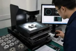
A coordinate measuring machine does not photograph a part or compare it to a master. It touches a finite number of points, fits mathematical geometry to those points, builds a coordinate system from the datums on your drawing, and reports where the fitted geometry sits relative to the tolerance. Every argument a buyer ever has with a supplier about dimensions comes back to one of those four steps, which is why understanding the CMM inspection process is worth more than memorising the accuracy figure on the machine’s data sheet.
This page walks the process in sequence, shows the two calculations that decide whether a result is trustworthy, and sets out the standards that govern each stage. Reading the resulting document is covered separately in our guide to CMM inspection reports, and the formal aerospace first article procedure in our guide to first article inspection to AS9102.
Key takeaways
- A CMM measures points and fits geometry to them. Without a datum reference frame from ISO 1101 or ASME Y14.5, the numbers have nothing to be relative to.
- Machine capability is declared as a formula, not a single number. Under ISO 10360-2 it reads E0,MPE = A + L/K, so permissible error grows with measured length — worked below.
- Temperature is a first-order error source. ISO 1:2016 fixes the reference temperature at 20 °C; a 5 °C excursion moves 100 mm of steel by about 0.006 mm.
- Conformity is a decision, not a reading. ISO 14253-1 sets out how measurement uncertainty is applied before a part is called good or bad.
- Every MW+ order ships with a certificate of conformance, a CMM inspection report on the critical dimensions and material certificates; AS9102 first article and PPAP Level 3 are quoted per programme.
- A CMM is the wrong instrument for surface texture, thread form and flexible parts. Specifying one where another is required is a common and expensive drawing error.
- What is a CMM actually measuring, and against what?
- The CMM inspection process, step by step
- How accurate is a CMM, really?
- Why 20 °C matters more than buyers expect
- Which parts get measured, and how many?
- Which standards govern the process
- What makes a drawing measurable?
- When a CMM is the wrong instrument
- How MW+ runs CMM inspection
- Frequently asked questions
What is a CMM actually measuring, and against what?
It measures the position of individual points on the part’s surface, each recorded as an X, Y and Z coordinate in the machine’s own frame. A bore is not measured as a diameter; a set of points around the bore is measured, and a circle or cylinder is fitted to them by least squares or by a minimum-circumscribed or maximum-inscribed criterion, depending on what the drawing calls for. The “diameter” you read on a report is a property of that fitted substitute geometry.
That fitted geometry then has to be placed somewhere. The datum reference frame does that job: the primary, secondary and tertiary datums on the drawing constrain the six degrees of freedom and give every subsequent measurement something to be relative to. Geometrical tolerances are defined in ISO 1101 and, in the North American convention, in ASME Y14.5. A drawing without a datum scheme cannot be inspected consistently, because two metrologists will align the part two different ways and get two different true-position results from identical point data.
The CMM inspection process, step by step
Six stages, in this order. The two that buyers rarely ask about — probe qualification and alignment — are the two that cause most disputed results.
| Stage | What happens | What goes wrong |
|---|---|---|
| 1. Programming | A routine is written from the CAD model and drawing, defining features, point counts and fit criteria | Features programmed to the model rather than the toleranced drawing |
| 2. Fixturing | The part is located and lightly restrained on the table, following the 3-2-1 location principle | Over-clamping distorts thin sections; under-restraint lets the part shift |
| 3. Probe qualification | The stylus tip is measured against a calibrated reference sphere to establish its effective diameter and position | Skipped after a stylus change, so every reading carries a fixed offset |
| 4. Alignment | Datum features are measured first and the part coordinate system is built from them | Aligning to convenient faces instead of the drawing datums |
| 5. Measurement | Points are taken by touch trigger or scanning; geometry is fitted to each feature | Too few points to characterise form; probing over burrs or coolant film |
| 6. Evaluation and reporting | Fitted geometry is compared to nominal and tolerance; results are dispositioned and recorded | Reporting deviation without stating the applied decision rule |
Why point count is a specification, not a detail
Three points define a circle exactly, which means three points can never reveal that the hole is lobed. Form errors only appear when enough points are taken to sample the shape, and scanning instead of touching raises that count by orders of magnitude. If roundness or cylindricity is toleranced on your drawing, ask how many points the routine takes on that feature; a report that shows a diameter in tolerance and says nothing about form may simply not have looked.
How accurate is a CMM, really?
Not as a single number. Machine performance is declared and verified under ISO 10360-2, which specifies acceptance and reverification tests for CMMs used to measure linear dimensions. The result is a maximum permissible error expressed as a length-dependent formula:
E0,MPE = A + L / K
A is a constant in micrometres, L is the measured length in millimetres, and K is a dimensionless constant. The error the machine is permitted to make therefore grows with the size of the measurement.
Worked example: permissible error at four lengths
Take a machine declared as A = 2.0 µm and K = 300. Substituting into the formula gives:
| Measured length L | L / K | E0,MPE = 2.0 + L/K | As a share of a ±0.005 mm tolerance band |
|---|---|---|---|
| 25 mm | 0.08 µm | 2.08 µm | 21% |
| 100 mm | 0.33 µm | 2.33 µm | 23% |
| 250 mm | 0.83 µm | 2.83 µm | 28% |
| 600 mm | 2.00 µm | 4.00 µm | 40% |
The last column is the point of the exercise. A common rule of thumb asks that the measurement system consume no more than about a tenth of the tolerance. On this machine a ±0.005 mm feature at 25 mm is comfortable; the same tolerance across a 600 mm span is not, and would need either a more capable machine, a shorter measurement path, or an explicit acceptance of the risk.
Uncertainty and who carries the risk
Because every measurement carries uncertainty, a reading close to a limit is ambiguous. ISO 14253-1 resolves this by defining decision rules: proving conformity requires the result to fall inside the tolerance by at least the uncertainty, and proving non-conformity requires it to fall outside by the same margin. In between lies an uncertainty range where neither can be proven.
The practical consequence is commercial rather than technical. Applied strictly, the supplier absorbs the uncertainty and the effective tolerance narrows; applied in reverse, the customer absorbs it. Agree which rule governs before the first lot ships, and have it written on the drawing or in the quality agreement. Most incoming-inspection disputes we see are not disagreements about the part at all — they are two organisations applying opposite decision rules to results that agree within a micron or two.
Why 20 °C matters more than buyers expect
ISO 1:2016 fixes 20 °C as the standard reference temperature for the specification of geometrical and dimensional properties. Every dimension on a drawing is, by default, a dimension at 20 °C. Measure the part at another temperature and you are measuring a different part.
Worked example: thermal expansion
Linear expansion follows ΔL = α × L × ΔT, where α is the coefficient of thermal expansion. For carbon steel, α ≈ 11.7 × 10⁻⁶ /°C. Over a 100 mm length with a 5 °C excursion:
ΔL = 11.7 × 10⁻⁶ × 100 mm × 5 °C = 0.00585 mm ≈ 0.006 mm
That is more than the whole of a ±0.0025 mm band, produced by nothing but a warm afternoon. Repeat the calculation in aluminium and it roughly doubles.
| Material | Nominal α (×10⁻⁶ /°C) | ΔL over 100 mm for ΔT = 5 °C |
|---|---|---|
| Titanium Ti-6Al-4V | 8.6 | 0.0043 mm |
| Carbon steel | 11.7 | 0.0059 mm |
| Stainless steel 304 | 17.3 | 0.0087 mm |
| Brass C36000 | 20.5 | 0.0103 mm |
| Aluminium 6061 | 23.6 | 0.0118 mm |
| PEEK | 47 | 0.0235 mm |
| Acetal / POM | 110 | 0.0550 mm |
Two operational consequences follow. Parts must be allowed to reach room temperature before measurement rather than being carried straight from a machine tool, and plastics need substantially longer to settle than metals. If you re-measure parts on arrival in an uncontrolled goods-in area, expect disagreement on tight features and treat it as an environment problem before treating it as a supplier problem.
Which parts get measured, and how many?
Three regimes, and the difference between them is a commercial decision that belongs in the purchase order rather than an assumption.
- Full dimensional inspection of every piece. Normal for prototypes and small batches, where there is no process history to rely on and the piece count makes it practical.
- First article, then sampling. One part is characterised across every feature, the process is accepted, and subsequent lots are sampled. The aerospace form of this is governed by AS9102.
- Attribute sampling by plan. Lot-by-lot sampling indexed by acceptance quality limit, per ISO 2859-1. Note that the current edition supersedes the 1999 edition still named on many older quality plans, so state which one governs.
Sampling is only defensible when the process has demonstrated it can hold the characteristic. That demonstration is a capability study under ISO 22514-2; MW+ works to a Cpk ≥1.67 target on controlled characteristics. Where no capability has been established, a sampling plan is a statement of hope rather than a control.
Which standards govern the process
| Standard | Governs | Where it bites in the process |
|---|---|---|
| ISO 10360-2 | Acceptance and reverification of CMMs for linear dimensions | Declares the machine’s permissible error |
| ISO 1:2016 | Standard reference temperature of 20 °C | Sets the condition every dimension implies |
| ISO 1101 / ASME Y14.5 | Geometrical tolerancing and datum reference frames | Defines the alignment and the evaluation |
| ISO 2768-1 | General tolerances where none is stated | Tells the programmer what untoleranced features must meet |
| ISO 286-1 | ISO code system for tolerances on linear sizes | Converts a fit call-out such as H7 into limits |
| ISO 14253-1 | Decision rules for conformity and non-conformity | Decides pass or fail near a limit |
| ISO/IEC 17025 | Competence of calibration laboratories | Underwrites the traceability of the reference artefacts |
| ISO 9001:2015, AS9100D, ISO 13485, IATF 16949 | Quality management systems by sector | Require calibration records and control of non-conforming output |
What makes a drawing measurable?
A measurable drawing answers the metrologist’s questions before they are asked. The items below are what a programmer looks for, and their absence is the usual reason a quotation comes back with queries instead of a price.
- A datum reference frame with primary, secondary and tertiary datums identified, not just a set of dimensions from an edge.
- Critical characteristics marked, so the inspection effort goes where function actually demands it.
- The general tolerance note stated explicitly — ISO 2768-m, for instance — so untoleranced features are governed by something.
- Form tolerances where form matters. A diameter tolerance does not control roundness, and a CMM will not report what the drawing does not ask for.
- The fit criterion for size features where it matters: least squares, maximum inscribed or minimum circumscribed give different answers on the same point cloud.
- The decision rule, or a reference to the quality agreement that carries it.
When a CMM is the wrong instrument
Surface texture
Ra, Rz and their relatives are profile parameters defined in ISO 21920-2, which supersedes the withdrawn ISO 4287, and in ASME B46.1. They require a profilometer with an appropriate stylus and cut-off, not a CMM. Specifying a surface finish and then asking for CMM verification of it is a category error. Our CNC surface finish chart covers what each grade means.
Threads and gear form
Functional thread acceptance is a gauge question. Go and no-go gauges assess the thread as it will be assembled; probing a helix on a CMM measures something related but not equivalent, and a part can pass one and fail the other.
Thin, flexible or springy parts
A touch probe applies force. On a thin wall or a compliant seal groove, the part deflects and the measurement records the deflection. Low-force scanning, optical measurement or a dedicated free-state definition on the drawing are the honest answers.
In-process control at volume
A CMM is deliberate and slow, and it usually sits in a separate room. On a running production cell, an air gauge or a bore gauge at the machine gives the operator feedback in seconds, and the CMM audits the result. Using a CMM as the primary feedback loop makes the loop too slow to correct anything.
How MW+ runs CMM inspection
MW+ has machined precision components in Shenzhen since 2015, from a 15,000 m² facility running 60+ CNC machining centres with 120+ engineering and quality professionals. Over a million parts have shipped to 50+ countries at a 99% on-time delivery record.
Inspection is programmed from the customer drawing rather than from the model alone, aligned to the drawing datums, and carried out in a temperature-controlled room referenced to 20 °C. General features are held to ±0.01 mm against ISO 2768-m, precision features to ±0.005 mm, and ±0.001 mm on selected features with dedicated fixturing. Every order ships with a certificate of conformance, a CMM inspection report covering the critical dimensions, and material certificates traceable to the mill heat number. First article inspection to AS9102 and PPAP Level 3 submissions are available on request and quoted per programme.
The wider metrology and documentation set is described under CNC machining quality control, the part families it applies to under CNC precision parts and custom machine parts, and the process list under CNC machining services. Work is carried out under ISO 9001:2015, AS9100D, ISO 13485, IATF 16949 and NADCAP accreditation.
Frequently asked questions
My incoming inspection disagrees with the supplier’s CMM report. Who is right?
Frequently neither, until three things are compared: the alignment used, the temperature at which each measurement was taken, and the declared capability of both instruments. Different datum alignments on the same part legitimately produce different true-position results. Start by exchanging the alignment definition and the ambient temperature, not by raising a non-conformance.
Is a CMM report proof that every part in the lot is good?
Only if the report covers every part. Otherwise it is evidence about the pieces measured plus a sampling argument about the rest. Ask which regime applied: full inspection, first article plus sampling, or an attribute plan. A report headed with a lot quantity and a sample size tells you immediately; one that does not should be questioned.
How tight a tolerance can a CMM actually verify?
It depends on the length being measured, because permissible error grows with length under ISO 10360-2. Work the formula for your feature rather than accepting a headline figure. As a working rule the measurement system should consume a small fraction of the tolerance band; if it consumes a third of it, the result is still useful but the decision rule near the limit matters a great deal.
Does 100% CMM inspection make sense for a production order?
Rarely, and asking for it can be counterproductive. It consumes inspection capacity that would otherwise go into process control, adds handling that risks damage, and buys less assurance than a capable process with a sound sampling plan. It is justified where a single escape is catastrophic, or where no capability has yet been demonstrated. Otherwise, ask for capability evidence instead.
Why does a CMM programme take so long to set up for a new part?
Because programming is engineering, not data entry. Each feature needs a fit criterion, a point strategy, a probe angle that can physically reach it, and an evaluation that matches the drawing call-out, and the whole routine has to be proven collision-free. It is paid once per part number and reused on every later lot, which is why repeat orders inspect far faster than the first one.
Can I ask for the raw point data rather than a summary report?
Yes, and it is a reasonable request when you intend to do your own analysis or compare fit criteria. Say so before the programme is written, because the point strategy that produces a clean summary is not always dense enough to support independent evaluation of form.
What should I check on a supplier’s calibration evidence?
That the machine has a current verification against ISO 10360-2 with the A and K values stated, that the reference artefacts are traceable through an accredited laboratory working to ISO/IEC 17025, and that probe qualification is recorded per session rather than per year. Those three items tell you more about a metrology function than any equipment list.