Most comparisons of CNC milling and turning start with the machines. This one starts with your part, because the machine is a conclusion, not a choice. Look at where the features sit relative to each other, and the process usually declares itself before anyone opens a quoting spreadsheet.
What follows is a design-led route to the decision: read the geometry, identify the datum the part wants, count the setups each process would need, and only then name the machine. The same method also tells you which small design changes move a part into the cheaper process without changing what it does.
Key takeaways
- Start from geometry, not from a machine list. If the principal features are concentric about a single axis, the part is a turning part. If they sit on two or more planes, it is a milling part.
- CNC turning produces concentricity as a by-product, because the stock rotates about the axis being cut. CNC milling has to achieve concentricity through fixturing and setup accuracy, which is why it is harder and dearer on rotational parts.
- Most real parts need both. Turning first, then milling the off-axis features against the turned datum, is usually cheaper and more accurate than the reverse order.
- Setup count drives cost and accuracy together. Each re-fixturing adds a relocation error to the stack-up, so a mill-turn or 5-axis route removing three setups often beats a lower hourly rate.
- MW+ holds general machining to ±0.01mm against ISO 2768-m, precision features to ±0.005mm and ±0.001mm on suitable geometry, with process capability of Cpk ≥1.67.
- Design changes move parts between processes. Replacing a square boss with a round one, or a cross-drilled pattern with an axial one, can delete an entire milling operation.
- Which process does your part geometry actually call for?
- What makes a part a turning part?
- What makes a part a milling part?
- Parts that need both, and why the order matters
- Setup count: the number that decides cost and accuracy
- What does each process do to tolerance and finish?
- Does the material change the answer?
- Design changes that move a part to the cheaper process
- When the obvious process is the wrong choice
- Frequently asked questions
Which process does your part geometry actually call for?
Ask one question of the model: can every principal feature be generated by rotating the part about a single axis? If yes, the part is a turning part. If the features sit on faces that are not concentric with one another, it is a milling part. CNC turning rotates the workpiece against a stationary tool; CNC milling rotates the tool against a held workpiece.
That single kinematic difference explains nearly every downstream consequence — which tolerances come free, which need fixturing to achieve, how many setups the part takes, and what it costs. The table maps common geometry descriptions onto the process each one calls for.
| Part geometry | Process it calls for | Why the geometry decides it |
|---|---|---|
| Shaft, pin, bushing, threaded body — all features about one axis | CNC turning services | Rotation about the axis generates the form; concentricity is inherent |
| Plate, housing, bracket — pockets and faces on separate planes | CNC milling services | Features have no common rotational axis, so the tool must move to them |
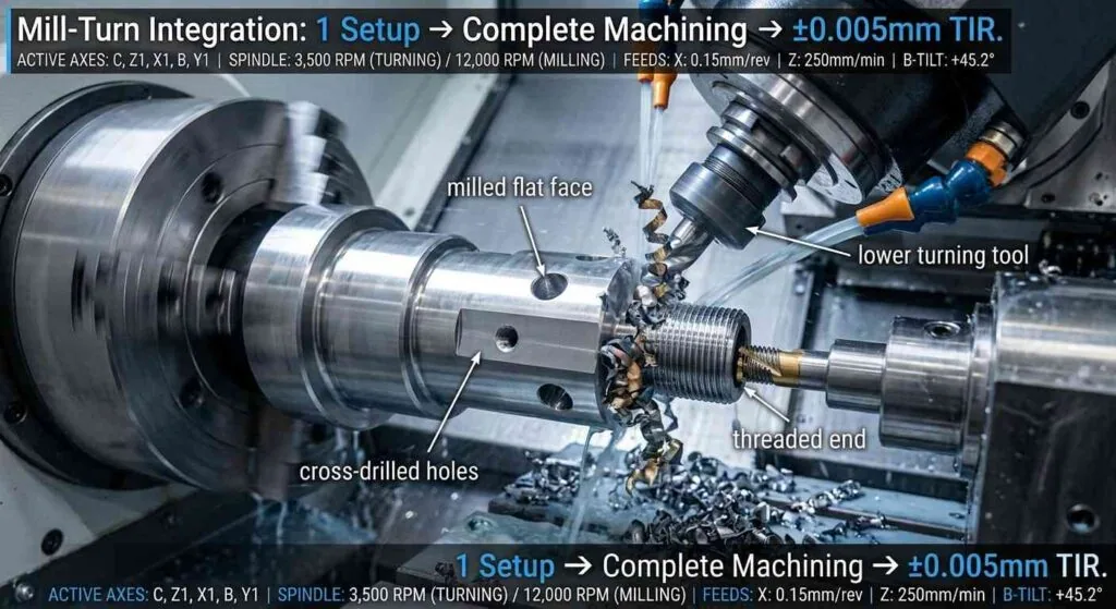
| Turned body with flats, cross-holes or a keyway | Turning followed by milling, or mill-turn in one machine | The rotational form dominates; the off-axis features are secondary operations |
| Small diameter, length above roughly 8 times diameter, high volume | Swiss machining | The guide bushing supports the bar at the cut, so slender stock does not deflect |
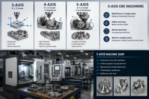
| Features on five faces, compound angles, sculpted surfaces | multi-axis machining | One setup reaches all faces, removing re-fixturing and its stack-up error |
What makes a part a turning part?
A part is a turning part when its functional features — outside diameters, bores, faces, grooves, threads and tapers — share a single axis of revolution. CNC turning is a process in which the workpiece rotates against a stationary single-point tool, so the cut sweeps a circle by definition. Roundness and concentricity therefore come from the process itself rather than from setup accuracy.
That matters most on parts where a bore and an outside diameter must be concentric — a bearing housing on a shaft, a valve body, a connector shell. Turned in one chucking, both surfaces reference the same spindle axis. Milled, they reference the fixture, and the fixture becomes an error source you have to control and inspect.
Turning also has a raw-material advantage on round parts. It starts from bar stock close to the finished diameter, whereas milling the same part from a block removes far more material for the same result, in machine time as well as scrap.
Worked example: how much metal each route actually removes
Take a plain cylindrical body, 40 mm diameter by 100 mm long, and compare the two blanks it could be made from. The arithmetic is geometry only, so you can run it on your own part before asking anyone for a price.
Step 1. Finished body: π × 20² × 100 = 125,664 mm³. Step 2. Turning blank, Ø45 mm bar cut to 100 mm: π × 22.5² × 100 = 159,043 mm³, so 33,379 mm³ is removed, or 21% of the blank. Step 3. Milling blank, a 45 × 45 × 100 mm block: 202,500 mm³, so 76,836 mm³ is removed, or 38% of the blank.
Step 4. Compare the two: the milled route removes 2.3 times as much metal, out of a blank 1.27 times heavier to buy. On an expensive grade such as Ti-6Al-4V, that blank difference alone can outweigh every other line in the quote.
Step 5. Read the limit of the result. The 2.3 figure is chip volume, not price; it sets a floor under the cycle time rather than predicting it. The gap widens further once concentricity between the bore and the outside diameter has to be achieved by fixturing instead of by the spindle, which is the part of the comparison no volume calculation captures.
What makes a part a milling part?
A part is a milling part when its features sit on planes that do not share a rotational axis — pockets, slots, bolt patterns, mounting faces at right angles to one another. CNC milling is a process in which a rotating multi-point cutter is driven across a held workpiece, so any feature the tool can reach and clear can be produced without the part needing symmetry.
The trade-off is that everything positional is now a fixturing question. A hole pattern on a milled face is only as accurate as the relationship between the fixture, the datum surface and the machine’s axes. That is why a milled drawing needs an explicit datum scheme per ISO 1101 or ASME Y14.5, in a way a simple turned part often does not. Our walkthrough of how CNC milled parts are made follows one through the shop from blank to inspection.
Reachability is a design constraint, not a shop problem
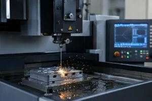
A milled feature must be reachable by a tool with enough length to get in and enough stiffness not to chatter. Deep narrow pockets, undercuts and sharp internal corners all fail this test. Sharp internal corners in particular cannot be milled at all, because a rotating cutter leaves a radius equal to its own — a detail that sends more parts to wire EDM services than any other.
Parts that need both, and why the order matters
When a part has both a rotational form and off-axis features, turn first and mill second. Turning establishes a true cylindrical datum that the milling operation can locate from, so the cross-holes and flats are positioned against a surface the machine itself created. Milling first and turning afterwards forces the lathe to re-find an axis that no longer has a clean reference.
Where volume justifies it, a mill-turn machine performs both in one setup, with live tooling doing the cross-drilling while the part remains in the same chuck. That removes the transfer entirely, which is the whole point: the error you never introduce does not need inspecting.
| Feature on the part | Process that produces it | Design note |
|---|---|---|
| Outside diameter, bore, face, groove, thread | Turning | Concentric features in one chucking need no positional tolerance between them |
| Flat, keyway, cross-hole, wrench flats | Milling, or live tooling on a mill-turn | Dimension these from the turned datum, not from another milled feature |
| Bolt circle on a turned flange | Milling or live tooling | State the bolt circle relative to the turned bore as datum |
| Sharp internal corner in hardened material | Wire or sinker EDM | A milling cutter always leaves its own radius; specify a corner relief if EDM is not wanted |
| Sculpted or compound-angle surface | 5-axis milling | One setup avoids re-fixturing error across the blended surfaces |
Setup count: the number that decides cost and accuracy
Setup count is the number of times a part must be unclamped and re-fixtured to complete it, and it drives cost and accuracy at the same time. Each setup adds labor, machine time and a relocation error that stacks with every other error in the chain. A part that runs in one setup carries no relocation error between its features; a four-setup part carries three.
This is why comparing hourly rates between processes misleads. A 5-axis or mill-turn machine has a higher rate and often produces the cheaper, more accurate part, because it deletes setups rather than running faster. Ask a quote to state the number of operations, not just the price. The price side of the same comparison is worked through separately in our note on CNC milling vs turning cost.
What does each process do to tolerance and finish?
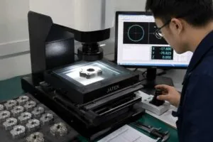
CNC turning holds concentricity, roundness and axial relationships better than milling on rotational parts, because the process generates them; CNC milling holds positional relationships across separate planes better, because the tool can be driven anywhere the fixture allows. Both processes at MW+ reach ±0.01mm generally, ±0.005mm on precision features and ±0.001mm on suitable geometry.
Surface finish is set by the finishing pass and the tool, not by the process family. MW+ produces Ra 3.2µm as-machined, Ra 0.4µm fine-machined and Ra 0.1µm polished. Texture parameters were defined in ISO 4287:1997, superseded by ISO 21920-2:2021, and drawings still use either convention, so state which governs. State the Ra value and the surface it applies to; a drawing that omits it leaves the finish to the machinist.
| Criterion | CNC turning | CNC milling | Which wins, and on what condition |
|---|---|---|---|
| Concentricity between a bore and an outside diameter | Inherent in one chucking | Depends on fixture and setup accuracy | Turning, whenever both features share one axis |
| Position of features across two or more planes | Requires live tooling or a second operation | Native to the process | Milling, whenever the features have no common axis |
| Material removed from stock | Bar stock close to finished diameter | Block stock, more material removed | Turning on round parts, on both cost and cycle time |
| Achievable general tolerance at MW+ | ±0.01mm to ISO 2768-m | ±0.01mm to ISO 2768-m | Neither; tolerance follows the feature, not the process family |
| Suitability for slender parts | Strong with a Swiss-type guide bushing | Weak; long thin parts deflect under the cutter | Turning, for length-to-diameter ratios above about 8:1 |
Does the material change the answer?
Material rarely changes which process the geometry calls for, but it changes how hard that process is to run and what it costs. Free-machining brass and aluminum 6061-T6 cut quickly in both processes. Stainless 316L work-hardens, so it prefers a heavier, uninterrupted cut. Titanium Ti-6Al-4V conducts heat poorly, pushing heat into the tool rather than the chip, which shortens tool life in both milling and turning.
Where material does influence the decision is in interrupted cuts. Milling is inherently interrupted — each flute enters and leaves the work on every revolution — so a material sensitive to thermal cycling or edge chipping runs better turned where the option exists. Nominal property values for these grades are published by sources such as MatWeb; work from the mill certificate when a property is load-bearing.
MW+ machines 70+ material grades across both processes. Specify the full designation and condition on the drawing — aluminum 6061-T651 rather than “aluminum” — because temper and heat treatment affect achievable tolerance more than the base metal name.
Design changes that move a part to the cheaper process
Small geometry changes can delete a whole operation. If a feature exists for assembly convenience rather than function, ask whether an equivalent feature on the rotational axis would serve — because moving one feature onto the axis can turn a two-process part into a one-process part, with the setup and its stack-up error removed.
| Design as drawn | Design change | Effect on manufacture |
|---|---|---|
| Square boss on a turned body | Make the boss round | Removes the milling operation entirely; the feature is turned with the body |
| Cross-drilled hole pattern | Move the holes to an axial pattern where function allows | Drilled on the lathe in the same chucking; no second setup |
| Sharp internal corner in a milled pocket | Add a corner radius matched to a standard cutter | Avoids an EDM operation and a separate supplier process step |
| Deep narrow pocket | Open the width or reduce the depth | Allows a shorter, stiffer cutter; faster and less prone to chatter |
| Two tight independent dimensions on a mating pair | Specify an ISO 286 fit class such as H7/g6 | States the functional clearance directly and quotes cheaper |
Fit classes are worth singling out. Where two parts have to slide or locate, an ISO 286 designation communicates the requirement better than two separately tightened bands, and it is usually cheaper to manufacture. Setting the drawing’s default note to ISO 2768-m and tightening only the three or four features that matter has the same effect.
When the obvious process is the wrong choice
The geometry-first rule has four known exceptions: very low quantities where fixture cost dominates, slender parts that need a guide bushing, thin-walled parts that deflect under any cutting load, and hardened material with sharp internal corners. In each case, the process the geometry suggests is not the process that produces the part economically or at all.
| Situation | Better route | Why the obvious choice fails |
|---|---|---|
| Quantity of five, rotational part needing a custom fixture for its milled features | Mill the whole part from block, accepting more material removal | The fixture costs more than the extra machining across five pieces |
| Slender turned part, length-to-diameter above roughly 8:1 | Swiss-type turning with a guide bushing | Conventional turning deflects the stock away from the tool as it cuts |
| Thin-walled part with a tight bore | Redesign for stiffness, or add a stress-relief step between roughing and finishing | The wall deflects under clamping and springs back after release |
| Hardened tool steel with sharp internal corners | Wire or sinker EDM | Spark erosion applies no cutting force and is not limited by cutter radius |
| Rotational part where the drawing tolerances are all loose | Whichever process the shop can schedule soonest | Below ±0.1mm the process choice stops affecting the result and only affects the date |
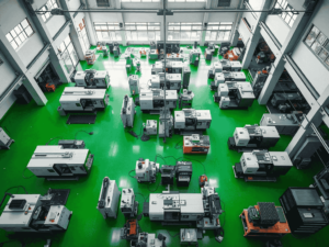
MW+ runs both processes in the same facility, across 60+ CNC machining centres at No. 39 Xishi Road, Hewan Community, Guangming, Shenzhen, with quotes returned within 24 hours and no minimum order quantity. The full range is set out on the CNC machining services page, and you can request a CNC machining quote with the drawing attached to get a process recommendation alongside the price.
Frequently asked questions
My part is round but has flats and cross-holes — should I quote it as turning or milling?
Quote it as turning with secondary milling, and dimension the flats and cross-holes from the turned diameter as datum. The rotational form is what the part is; the flats are features added to it. Sending the same drawing out as a milled part invites a quote that removes far more material and holds concentricity worse, for a higher price.
Why is my milled part quoted higher than the turned version of the same design?
Two reasons usually dominate. Milling a round part starts from block stock, so more material is bought and more of it becomes chips. And milling often needs additional setups to reach features that a lathe reaches in one chucking, each adding time and inspection. Ask for the quote broken into material, setups and machining time to see which of the two applies.
Does mill-turn always beat separate turning and milling operations?
No. Mill-turn wins when the part has enough off-axis features that eliminating the transfer saves real time and error, which usually means moderate to high volume. At low quantities the programming time for a mill-turn cycle can exceed the time saved, and two simpler operations on separate machines quote lower. Volume, not sophistication, decides it.
How do I tell the supplier which surface is the datum?
Mark it explicitly on the 2D drawing using a datum scheme per ISO 1101 or ASME Y14.5, and choose the surface the part is functionally located from in the assembly. On a turned-then-milled part the turned diameter or a turned face is normally the right datum, because it is the surface the milling setup will locate against.
Can the same tolerance be held by both processes?
General tolerances are the same across both at MW+, at ±0.01mm against ISO 2768-m. What differs is which tolerances are easy. Concentricity between coaxial features is close to free in turning and expensive in milling; positional tolerance across separate planes is native to milling and needs live tooling or a second operation in turning. Match the tolerance you tighten to the process that produces it naturally.
Should I choose the process, or let the supplier choose?
State the geometry, the datums and the functional tolerances, and let the supplier propose the process. Specifying a machine type on the drawing constrains the quote without improving the part, and it occasionally blocks a better route the shop can see. What you should specify is intent: which features mate, which surfaces locate, and what has to be concentric with what.
Do I need to prototype before committing to a process?
Prototype when the design has not yet been validated in an assembly, because a fit problem found on paper costs nothing and the same problem found in production costs a batch. CNC prototyping at MW+ runs 3–5 business days, with a 48-hour express route, and there is no minimum order quantity, so a single validation piece is a normal order rather than a favor.