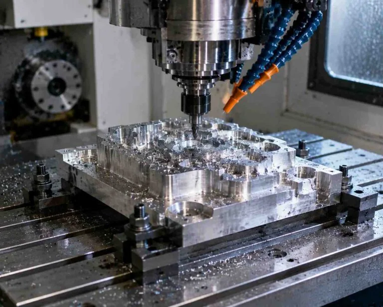








Select deburring methods by the edge that must be delivered, the material, tool access and the evidence needed for acceptance. Removing an attached burr, producing a defined chamfer and conditioning an internal surface are different objectives. Supplier descriptions of mechanical, abrasive, thermal and electrochemical processes illustrate those distinctions; none establishes that a process is suitable for every component. [1] [3] [4] [5]
This guide explains how to turn a burr-removal request into a reviewable manufacturing and inspection plan. It covers bore entrances, accessible edges and intersecting holes. It does not assign universal edge dimensions, select a fastener seat or qualify a hydraulic assembly. The numerical example is an original, hypothetical geometry calculation, not a recommended specification, a measured part or a completed MetalWorksPlus project.
Contents
Deburring methods start with the required edge
Begin the review with an edge map on the released drawing or model. Identify each relevant external perimeter, bore entrance, bore exit and internal intersection. Give the edges stable identifiers so that a process proposal, inspection image and nonconformance report can refer to the same location. Make exceptions visible where an edge must retain a specific geometry.
Next, describe the intended result. Is the requirement to remove attached material, limit an undefined edge departure, produce a specified chamfer, or create a controlled radius? ISO’s public abstract for ISO 13715 distinguishes undefined-edge indication from a geometrically defined edge. [6] Use the governing drawing standard and approved edition for the actual callout; the abstract does not replace its normative rules.
A useful engineering recommendation is to separate the edge’s function from its manufacturing method. For example, identify whether the edge borders a locating bore, seal land, assembly lead-in or handling surface. Then ask the responsible designer what finished condition is required and how much surrounding material may be removed. Avoid converting every “remove burrs” note into the same unapproved chamfer.
Record the material and its condition at the operation. Ask whether deburring is proposed before or after heat treatment, coating and other finishing steps. Define the acceptance stage explicitly. A supplier should be able to explain which requirements are checked immediately after deburring and which are checked on the delivered component.

Compare material-removal mechanisms and access
Compare processes against the same edge map and acceptance requirements. The following table summarizes manufacturer-described mechanisms and adds original review questions. It is a selection aid rather than a capability statement about MW+. Confirm actual availability, application limits and qualification responsibilities before specifying a route.
| Method family | Documented mechanism | Question for the component review |
|---|---|---|
| Mechanical cross-bore tooling | Dedicated cutting-tool solutions address intersecting bores. [1] | Can the proposed tool reach and follow every controlled intersection edge? |
| Flexible abrasive honing | A flexible abrasive tool can remove burrs and condition a bore surface. [2] | Are the resulting edge blend and adjacent surface changes acceptable? |
| Abrasive flow machining | Abrasive media flows over targeted surfaces and edges. [3] | How will the fixture and media path control where material is removed? |
| Thermal deburring | Combustion in a chamber removes burrs through oxidation. [4] | Is the component/process combination approved, and how are residues treated? |
| Electrochemical deburring | Current and electrolyte enable anodic material dissolution near a cathode. [5] | How are the target region, gap and adjacent surfaces controlled? |
Mechanical cutting and accessible-edge work
HEULE describes application-specific tools for crossbores and distinguishes several intersection arrangements, including custom developments. [1] The practical lesson is to review the actual bore relationship rather than select a tool from the word “cross-hole” alone. A through-hole entrance and an offset internal intersection should not share an assumed access solution.
For accessible edges, ask the supplier to identify the proposed cutting or hand-finishing operation and its acceptance controls. Request a clear boundary between permitted local rework and a change requiring engineering approval. When manual work is proposed, include the edge map, approved tools or procedure, and a record of the final inspection. Do not accept operator discretion as the only definition of the finished edge.
Abrasive conditioning and controlled surface change
Brush Research describes flexible honing as a way to address cross-hole burrs while modifying surface finish and producing blended edges. It does not position the tool as a heavy material-removal process. [2] Before choosing this route, ask for evidence that the starting burr condition and desired final edge fit the proposed tool and procedure.
Extrude Hone describes abrasive flow machining as media-based surface and edge conditioning. Its process description identifies flow, media characteristics and workpiece properties as material-removal variables. [3] For a proposed application, request a fixture and flow-path explanation, the surfaces intentionally exposed, and a plan for checking features that must remain within their drawing requirements.
Do not treat a smoother surface as automatic proof of a conforming edge. Ask separate questions about the controlled edge profile, nearby bore dimensions and the specified texture. When those characteristics need different acceptance records, list them separately in the inspection plan.
Thermal and electrochemical routes
Extrude Hone’s thermal description uses combustion and oxidation to remove burrs. It also describes oxide residue and subsequent removal options. [4] A process proposal should therefore explain both the deburring operation and the delivered surface condition. Do not substitute a broad vendor statement about removal for component-specific acceptance evidence.
Its electrochemical description uses the workpiece as an anode, a cathode tool and an electrolyte. Tool geometry and the working gap help determine where removal takes place. [5] Ask the processor to identify the target region and explain how the component’s other requirements will be protected and verified. This article supplies no electrolyte, current, cycle or fixture recipe.
Cross-hole deburring: map the complete intersection
For an internal intersection, prepare a sectioned model view showing the main bore, intersecting bore, their centerlines and the controlled edge. Include bore dimensions, depths, intersection angle, offsets and the available approach path. Ask the tool or process supplier to confirm the complete geometry rather than approving a method from one outside photograph.
Then identify what the inspector must see or measure. Mark each edge segment on the section view and link it to an inspection view or other approved verification method. Where direct observation is proposed, ask the inspector to demonstrate coverage of the relevant circumference and explain any obscured region. An unviewed region should remain an open verification issue.
Use the same map during process trials. Record starting condition, operation sequence and final observations against edge identifiers. If only a few trial pieces are examined, report their actual scope; do not turn a limited trial into an unsupported claim that every production edge is conforming. Agree production controls and sampling with the responsible quality team.
For a manifold-specific drawing, keep this edge review connected to the broader passage and assembly requirements. The existing hydraulic manifold machining guide provides that application context. This article stays focused on deburring selection and verification rather than reproducing its material, pressure or circuit-design discussion.
Edge break specification: a checked geometry example
Assumed inputs: Consider an ideal cylindrical through-bore of diameter D = 6.00 mm through a plate of thickness L = 8.00 mm. For this geometry exercise only, add a continuous equal-leg 45° chamfer at one entrance. Leave the opposite end geometrically unchanged. Let c be both the radial enlargement and axial depth of that chamfer, not its sloping face width.
By the defined equal-leg geometry, the entrance diameter is D + 2c and the remaining full-diameter cylindrical length is L − c. The sloping face width is c√2. These relationships follow from the stated right-triangle model; the inputs and calculated outputs below are hypothetical. No burr size, process capability or acceptable chamfer range is implied.
| Assumed chamfer leg c, mm | Calculated entrance diameter, mm | Calculated cylindrical length, mm | Calculated sloping width, mm |
|---|---|---|---|
| 0.10 | 6.20 | 7.90 | 0.1414 |
| 0.20 | 6.40 | 7.80 | 0.2828 |
| 0.30 | 6.60 | 7.70 | 0.4243 |
The middle row can be checked directly: 6.00 + 2 × 0.20 = 6.40 mm; 8.00 − 0.20 = 7.80 mm; and 0.20 × √2 = 0.2828427 mm. A sloping-width measurement of approximately 0.283 mm therefore does not mean the chamfer leg is 0.283 mm. Define the dimension being inspected before comparing a result with the drawing.
For an additional hypothetical tolerance check, suppose the designer writes c = 0.15 ±0.05 mm while D and L remain exact in the teaching model. Then c ranges from 0.10 to 0.20 mm, the entrance diameter from 6.20 to 6.40 mm, and the cylindrical length from 7.80 to 7.90 mm. In a real stack, include the actual bore, thickness, angle and geometric variations; this simplified calculation is not a release decision.
Use the example to review a functional question: how much of the original full-diameter length is required? If the designer needs a controlled engagement or land, agree that requirement before accepting an edge treatment. Do not apply this rotationally symmetric entrance model to a curved internal cross-hole intersection; that edge has a different geometry.
Plan inspection and final condition together
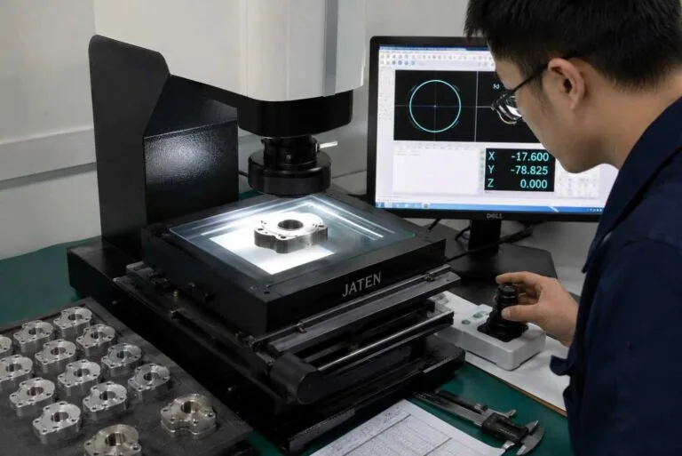
Our recommended inspection plan separates four questions: was attached material removed to the approved criterion, is the edge shape conforming, are neighboring features still acceptable, and is the required final condition documented? Choose an appropriate verification method for each question. A single general photograph should not be assigned more evidential value than it provides.
For a visible edge, agree the observation conditions, viewing direction, required coverage and acceptance examples. Where a numerical size is required, identify the measurement definition and method, including its suitability for the actual geometry and tolerance. If an image is retained as evidence, record its edge identifier and scale or measurement context where applicable.
For an internal edge, ask the inspector to demonstrate access on the actual part or an approved representative configuration. Record regions that cannot be verified by the proposed arrangement. Consider whether a different viewing method, a representative sectioned trial piece or another approved verification approach is needed. A destructive trial section is a proposal for engineering approval, not a routine instruction to cut a production component.
After processing, confirm that neighboring bore, land, thread and surface requirements remain within scope. Keep final cleaning and cleanliness requirements explicit where the application requires them. For thermal deburring in particular, residue treatment belongs in the approved route because the manufacturer describes oxide formation. [4] This guide does not assign a universal cleanliness class or imply that visual inspection proves particle cleanliness.
Include the edge map in the quality assurance discussion so the requested inspection record refers to the same controlled features.
Release a useful manufacturing and inspection brief
Before quotation or process approval, use this checklist to close the interface between design, manufacturing and quality:
- Scope: Identify material condition, drawing revision and every controlled edge, including exceptions.
- Result: Distinguish burr-removal criteria, undefined-edge limits and geometrically defined edge requirements.
- Access: Supply bore geometry, section views and the proposed tool or process approach.
- Protection: Identify features that must retain their dimensions and surface condition.
- Sequence: State when deburring, finishing, cleaning and final acceptance occur.
- Evidence: Agree inspection coverage, measurement definitions, records and disposition of inaccessible regions.
- Change control: Require review when the method, starting condition or critical edge requirement changes.
For a component enquiry, identify the edge requirements within MW+’s precision component range, then discuss the proposed sequence through its CNC machining service review. Send MetalWorksPlus the drawing, model and edge map together with the required inspection record. Confirm the available process and any specialist subcontracting or validation separately; the method comparison above is not a list of verified MW+ equipment.
Frequently asked questions
Which deburring method is best for cross-holes?
No method is selected from the label alone. HEULE offers geometry-specific cross-bore solutions, while abrasive and other processes use different removal mechanisms. [1] [3] Review actual access, material, desired edge and acceptance evidence before approving a route.
Does burr removal always require a chamfer?
Do not assume that it does. Define whether the drawing requires removal of attached material, an undefined-edge condition or a specific geometric shape. ISO’s public scope distinguishes undefined from geometrically defined edges. [6] A required chamfer should be dimensioned under the applicable drawing rules.
Can an abrasive brush be assumed to preserve every bore dimension?
No. BRM describes both burr removal and surface conditioning. [2] Require component-specific evidence that the finished bore, edge and adjacent surfaces satisfy the released drawing rather than transferring a general product description into an acceptance result.
Is the example chamfer a recommended edge break specification?
No. The 6 mm bore, 8 mm thickness and chamfer sizes are assumed solely to explain geometry and measurement definitions. They establish no universal value, inspection tolerance or acceptable product design.
Does a successful process cycle prove an internal edge is acceptable?
Use a cycle record as process evidence, then evaluate the finished edge against the agreed acceptance and coverage plan. Keep any unverified region visible in the release review. Neither the process name nor an unrelated inspection photograph documents that particular edge.
Technical references
- HEULE: X-BORES. Mechanical tooling for intersecting bores; application-specific and custom solutions. No tool limit transferred to MW+.
- Brush Research Manufacturing: Automated Deburring for Cross-Drilled Holes. Flexible abrasive honing can address burrs and surface finish; blended edges; not heavy stock removal.
- Extrude Hone: Abrasive Flow Machining. Abrasive media conditions edges and surfaces; flow, media and fixture influence material removal.
- Extrude Hone: Thermal Deburring Technology. Chamber combustion/oxidation removes burrs; oxide residues require follow-on treatment. No temperature/process recipe or complete-removal guarantee adopted.
- Extrude Hone: Electrochemical Deburring. Anodic dissolution using cathode, electrolyte and current; gap and tooling determine removal location.
- ISO 13715:2017: Edges of Undefined Shape. Public abstract distinguishes undefined-edge indication from geometrically defined edges. Full normative text not accessed; no symbol rules reproduced.
Sources reviewed on 25 October 2026. Supplier descriptions support process principles only. Review questions are engineering recommendations; the calculations use explicitly assumed inputs and do not represent MW+ production or test results.