








Boring vs reaming is a choice about how an existing hole is brought to its finished requirements, not a reliable shortcut for specifying those requirements. Boring enlarges or finishes an existing hole; reaming finishes a prepared hole using a multi-edge tool. Both need an appropriate setup and an inspection plan. Sandvik’s process overview makes that distinction without establishing a tolerance for every possible component. [1]
For engineers and procurement teams, the useful question is which coordinated operations can produce the specified diameter, location, form, surface and controlled depth. Select the route against the actual material and geometry. Do not assume a process name guarantees bore accuracy or that one method is always the less expensive choice.
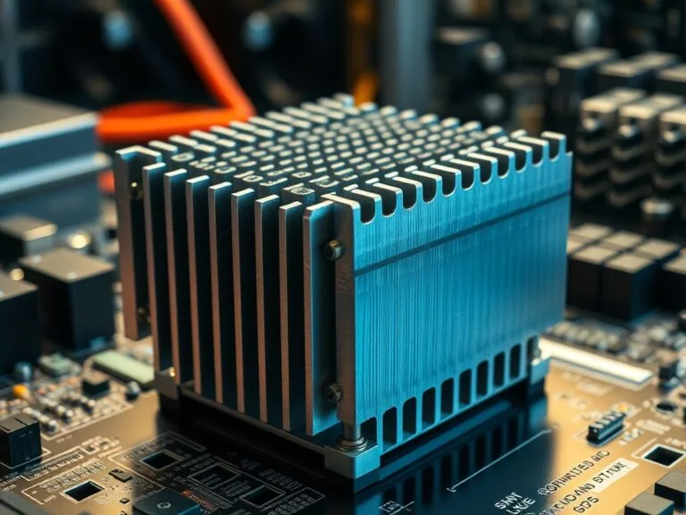
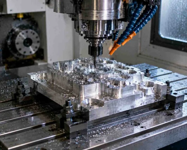
This educational guide uses hypothetical dimensional examples to explain stock allowance and inspection limits. They are original teaching calculations, not recommended cutting data, measured MW+ results or an approved part design. Existing library images illustrate component and machining contexts without proving which operation produced a particular hole.
Contents
Boring vs reaming: understand the process distinction
Boring works on a hole that already exists. Sandvik describes fine boring as a finishing operation used for close hole size, positioning and surface requirements, with adjustable tool arrangements. [4] The actual tool, available stock, machine and setup determine what can be corrected in a specific part; the process name alone establishes none of those results.
Reaming is a finishing operation using multiple cutting edges. [1] Its dependence on the prepared hole is especially important: Sandvik states that reaming should not be expected to correct positional or straightness errors in that hole. [2] A diameter improvement is therefore not evidence that an incorrectly located feature has moved into its required position.
| Decision question | Boring review | Reaming review |
|---|---|---|
| What is the starting feature? | Existing hole with a defined stock condition. | Prepared hole suitable for the selected reamer. |
| What needs correction? | Review size, location and form against the actual setup and remaining material. | Do not rely on reaming to correct prepared-hole position or straightness. |
| What controls the result? | Tool setting, rigidity, cutting conditions and geometry. | Prepared-hole condition, tool selection, alignment and operating conditions. |
| What proves acceptance? | Characteristic-specific inspection against the released drawing. | |
Our recommendation is to compare complete process proposals for the same finished feature. A proposal that changes the controlled depth, tolerance or surface condition should be reviewed as a design change, not silently accepted as an equivalent way of making the original part.
Also clarify the proposed machine arrangement. An internal turning operation on a rotating component and a rotating boring tool on a machining center are different setups. Ask the supplier to identify the arrangement actually proposed and the relationship it establishes between the bore and the component datums.
Define the finished hole before choosing the tool
Prepare a characteristic list instead of writing only “ream to size.” Our recommended list separates diameter limits, controlled length, axis location, orientation, form, surface texture and entry condition. State the governing drawing reference and finished part condition. Identify the mating component or assembly requirement without leaving the supplier to invent the functional limits.
Reamed hole tolerance is a drawing requirement
Do not substitute a generic process-tolerance chart for the actual requirement. In our proposed review workflow, a numerical diameter band belongs on the controlled drawing, while the supplier explains how the proposed sequence will meet it. Request clarification whenever the model, drawing and quotation use different limits.
For a hypothetical example, assume the released diameter band is 20.000–20.020 mm over a separately defined length. The total size interval is 0.020 mm, or 20 µm. Those numbers are assumed here and are not an ISO fit designation, a suggested tolerance for every bore or evidence of MW+ capability.
Keep surface texture separate from geometry. KEYENCE’s cylindricity discussion concerns cylindrical form and describes form-measuring equipment and CMM approaches. [6] Our recommendation is to list any required form result separately from diameter and surface readings, with an agreed evaluation method for each.
Identify whether finishing, coating or subsequent assembly changes the controlled condition. Request the exact inspection stage on the drawing or quality plan. Do not compare a before-treatment measurement with an after-treatment limit without an approved dimensional relationship between those stages.

Review the prepared hole and stock allowance
Reaming requires a suitable amount of material to remove. Sandvik warns that too little stock can cause rubbing and wear, while too much is also undesirable. [3] That guidance explains why the prepared-hole dimensions belong in process planning; it does not provide one allowance that applies to every material and reamer.
Obtain the selected toolmaker’s applicable stock guidance and define whether it is radial or diametral. Our recommendation is to record the pre-machining limits, tool family, work material and relevant conditions together. Resolve the units and meaning before choosing a drill size or accepting a supplier’s preparation drawing.
Worked example: diametral removal versus radial allowance
Retain the assumed finished limits of 20.000–20.020 mm. Assume an ideal concentric, circular prepared hole measuring 19.750–19.800 mm. Treat these as exact input intervals for this arithmetic exercise, neglecting form, location, measurement uncertainty and thermal effects.
The minimum diametral difference is 20.000 − 19.800 = 0.200 mm. The maximum is 20.020 − 19.750 = 0.270 mm. For the assumed concentric circles, the corresponding radial difference is half the diameter difference: 0.100–0.135 mm per side.
| Hypothetical quantity | Calculation or assumed limits | Result |
|---|---|---|
| Finished hole diameter | Assumed drawing band | 20.000–20.020 mm |
| Prepared hole diameter | Assumed circular, concentric pre-hole | 19.750–19.800 mm |
| Smallest diametral difference | 20.000 − 19.800 | 0.200 mm |
| Largest diametral difference | 20.020 − 19.750 | 0.270 mm |
| Ideal radial difference | Half each diametral extreme | 0.100–0.135 mm per side |
The table makes a unit distinction and exposes the interval extremes. It does not establish that the selected reamer will cut correctly or produce the finished band. Ask the tool supplier to assess the actual material, preparation and application; then incorporate any approved change into the process specification.
Concentricity is a critical assumption in that example. An offset or distorted pre-hole does not leave the same stock around its circumference. We recommend reviewing a section or model of the actual starting geometry rather than treating half the nominal diameter difference as the minimum stock everywhere.
Where hole location or straightness is unacceptable, return to the preparation and finishing strategy. Sandvik specifically cautions against expecting reaming to correct those errors. [2] Consider a reviewed boring or other approved route, but obtain evidence that the proposed setup and remaining material can address the defect before accepting a recovery plan.
Coordinate access, stability and chip removal
For boring, Sandvik emphasizes short overhang, appropriate coupling and effective chip control, including the particular difficulty of clearing chips from blind holes. [5] For the enquiry, request a tool-access review that includes the complete assembly, entrance, shoulder, deepest controlled region and withdrawal path.
For reaming, Sandvik lists material, runout, offset, clamping, coolant and toolholding among the relevant variables. [3] Ask for guidance for the selected tool and hole type. An arrangement acceptable for one through-hole should not automatically be transferred to a blind hole or interrupted cut.
Separate tool adjustment from proven hole size
Sandvik explains that radial tool deflection affects machined hole diameter and recommends checking final fine-boring adjustment against a measured hole while the tool remains in the spindle. [4] A dial setting or preset value is therefore a process input to verify, not the finished-part inspection result.
As a separate ideal geometry check, moving a circular cutting radius outward by an assumed 0.004 mm would increase the generated diameter by 0.008 mm because diameter equals twice radius. This arithmetic is not an instruction to turn a particular boring-head dial by four divisions. Actual heads can indicate different quantities and require their own documented adjustment procedure.
Our recommended setup review also names the workholding references, supported surfaces and part state during finishing. Ask whether a controlled free-state feature is being assessed under a defined clamping condition. Resolve any proposed change to the inspection state before accepting the process.
Chip control belongs in the machining plan. Sandvik associates chip jamming and recutting problems with hole quality and tool reliability. [5] Request the proposed evacuation and cleaning approach, especially where a blind end or cross-hole restricts exit. Define edge-condition and cleanliness acceptance rather than leaving them as an unspecified final cleanup.
Plan diameter and geometric inspection separately
Select the measuring method before releasing an inaccessible bore. Mitutoyo’s bore-gage brochure describes different measuring ranges, access configurations and setting-ring arrangements. [7] Our recommendation is to confirm range, contact geometry, reach, reference setting and applicable calibration rather than assuming any instrument labeled “bore gauge” can evaluate the feature.
For diameter checks, agree the measurement depths and orientations. Record the actual feature identifier and part condition. If the method reaches only a portion of the controlled length, report that limitation explicitly and obtain an approved method for the remainder.
A small reading set is not a full form assessment
Imagine four assumed local diameter readings: 20.006, 20.008, 20.014 and 20.012 mm. Each displayed number lies within the illustrative 20.000–20.020 mm size band; their numerical spread is 20.014 − 20.006 = 0.008 mm. This original example describes the displayed readings only, with no measurement uncertainty or acceptance rule assigned.
The spread is not a computed cylindricity value and does not prove the entire bore meets every requirement. KEYENCE describes cylindricity as a form evaluation with dedicated measuring arrangements. [6] Our recommendation is to obtain the sampling and evaluation plan appropriate to the specified characteristic instead of renaming a diameter-reading range as a geometric result.
Keep axis location and orientation tied to the specified datum system and measurement plan. A diameter report alone does not document that separate evaluation. Ask which result demonstrates each drawing characteristic, and identify any missing datum setup or inaccessible feature in the review record.
Before accepting production evidence, request the drawing revision, measurement method, reference artifact or instrument identity, relevant calibration status and agreed decision rule. The proposed report should distinguish raw observations, evaluated results and acceptance decisions. No inspection or capability study has been performed for this article.
Choose a reviewable precision hole machining route
Our recommended selection sequence starts by listing the required output, then comparing proposals against the same controlled feature. Record which operation prepares location and stock, which operation finishes size and surface, and how the final component will be inspected.
- If size is the main finishing question, compare a specified reaming proposal with the required preparation and access.
- If location, stock distribution or form needs attention, request a coordinated preparation and finishing review.
- If inspection access is unresolved, close that issue before selecting a route based on price.
- If a supplier proposes changing a drawing requirement, obtain design approval before manufacture.
Compare quotation scope as well as unit price. Ask whether preparation, dedicated tooling, setting, inspection, cleaning and treatment-stage checks are included. Do not assume a universal cycle-time advantage, cost saving or minimum order quantity from either process label.
Keep this article separate from a specific fit-design exercise. A housing or locating-pin application requires its own functional limits and tolerance review. This guide focuses on obtaining and verifying a finished hole; it does not assign a fit to a real mating assembly.
Frequently asked questions
Can reaming correct a misplaced hole?
Do not rely on it. Sandvik states that reaming should not be expected to correct prepared-hole position or straightness errors. [2] Ask for a separately reviewed recovery or revised manufacturing sequence before accepting the feature.
Is boring always more accurate than reaming?
A process name does not establish a finished result. Compare the actual tool, material, geometry, setup and agreed inspection requirements. The article provides no universal accuracy ranking or MW+ capability figure.
How much material should be left for reaming?
Use the applicable toolmaker guidance for the selected tool, material and hole. Too little and too much stock can both be problematic. [3] The 0.100–0.135 mm radial interval above is an assumed calculation, not that guidance.
Does a passing diameter result prove cylindricity?
It does not document the separate form evaluation. Obtain the method and result specified for cylindrical form. [6] The hypothetical 0.008 mm spread is only the range of four displayed diameter readings.
Must I specify boring or reaming on the drawing?
Our recommendation is to define the functional output clearly and retain any justified process restriction required by the design authority. Ask the manufacturing supplier to propose its route, and approve any change to a controlled requirement before work begins.
Prepare a manufacturing enquiry
For machined mechanical components with controlled bores, include the material condition, model, drawing, functional references and inspection requirements. Identify the finished stage and any limits on access or subsequent treatments.
When requesting CNC support for the coordinated hole-making sequence, ask for the proposed preparation, finishing and verification scope. Where internal turning is relevant, the turning service overview provides process context; confirm the actual operation and quoted scope for the component.
A MetalWorksPlus enquiry is most useful when the required feature and evidence are explicit. For the broader drawing language, the GD&T symbols guide explains how to read the controls. Resolve missing requirements before comparing manufacturing proposals.
Technical references
- Sandvik Coromant: Boring and Reaming Tools.
- Sandvik Coromant: How to Ream a Hole.
- Sandvik Coromant: Reaming.
- Sandvik Coromant: Finish Boring.
- Sandvik Coromant: How to Apply Boring.
- KEYENCE: Measuring Cylindricity.
- Mitutoyo: Inside Diameter Measurement Bore Gage.
Manufacturer sources support the identified process and measurement distinctions. Vendor tool settings, historical product ratings and capability examples are not MW+ specifications. Numerical examples here use disclosed assumptions and require application-specific review.