The choice between 3-axis and 5-axis CNC machining is not a question about which machine is better. It is a question about one specific part, and it can usually be settled in a few minutes by counting faces, looking for compound angles, and working out how many times the part would have to be re-clamped.
This page is a decision guide. It gives you the tests to apply in order, a decision matrix you can hold your own part against, the cost logic behind the answer, and the cases where 5-axis is the wrong call even though the geometry looks like it wants it.
Key takeaways
- Count the faces that carry features. One or two faces means 3-axis. Three or more, or any compound angle, points to 5-axis.
- The deciding number is setup count, not machine hourly rate. Each re-fixturing adds a relocation error to the stack-up, so a part running in one 5-axis setup can be both cheaper and more accurate than the same part in four 3-axis operations.
- 3+2 positional machining — index the part, lock the rotary axes, cut in three axes — covers most multi-face parts. Full simultaneous 5-axis is only needed for sculpted and compound-angle surfaces.
- MW+ holds general machining to ±0.01mm against ISO 2768-m, precision features to ±0.005mm and ±0.001mm on suitable geometry, with process capability of Cpk ≥1.67, on both 3-axis and 5-axis routes.
- 5-axis is the wrong choice on simple prismatic parts, on very low quantities where programming time dominates, and on parts whose real problem is sharp internal corners in hardened material — that is an EDM job.
- Send a STEP file plus a dimensioned drawing with datums and let the supplier recommend the axis count. MW+ returns a quote within 24 hours and applies no minimum order quantity.
- How do you choose between 3-axis and 5-axis CNC for your part?
- What 3-axis and 5-axis machines actually do differently
- Test one: how many faces carry features?
- Test two: are there compound angles or sculpted surfaces?
- How setup count changes tolerance, not just cost
- What does 5-axis cost, and when does it pay for itself?
- Worked example: counting the setup break-even
- Worked examples: which parts belong on which machine
- When 5-axis is the wrong choice
- What to send so a supplier can recommend the axis count
- Frequently asked questions
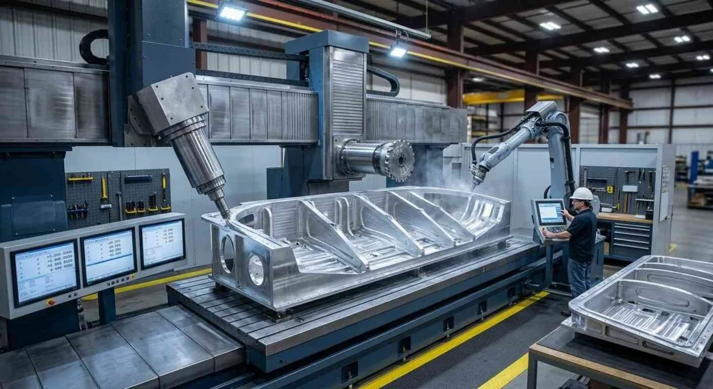
How do you choose between 3-axis and 5-axis CNC for your part?
Apply four tests in order. Count the faces that carry features; look for compound angles, undercuts or sculpted surfaces; work out how many setups a 3-axis route would need; then check the quantity. A part with features on one or two faces belongs on 3-axis. A part needing three or more setups, or carrying any compound angle, belongs on 5-axis.
The matrix below is the short version. Hold your own part against the left-hand column and read across.
| Your part | Recommended route | Why |
|---|---|---|
| Features on one or two faces, all reachable from above | 3-axis milling | Lowest machine rate, shortest programming, no benefit from rotary axes |
| Features on three to five faces, all at right angles | 3+2 positional 5-axis | One setup reaches every face; the rotary axes index and lock, so cutting is still 3-axis |
| Compound angles, blended or sculpted surfaces, impellers, manifolds | Simultaneous 5-axis | The tool axis must tilt while cutting to keep the cutting edge in contact correctly |
| Deep pocket needing a long tool from above | 5-axis, tilting the head to shorten the tool | A shorter, stiffer tool cuts faster and chatters less than a long one |
| Sharp internal corners in hardened steel or carbide | Wire EDM services, or sinker EDM | No cutter of any axis count can produce a corner sharper than its own radius |
What 3-axis and 5-axis machines actually do differently
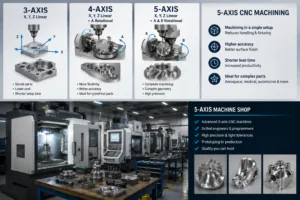
A 3-axis machining center moves the cutting tool along three linear axes — X, Y and Z — with the tool always pointing in the same direction relative to the workpiece. A 5-axis machining center adds two rotary axes, so the tool or the table can tilt and turn, letting the tool reach faces that are not facing the spindle and letting the tool axis change while cutting. The kinematics behind that, and what a trunnion table does to the working envelope compared with a swivel head, are covered in our explainer on how 5-axis machining works. This page assumes that background and deals only with the choice.
3+2 positional versus full simultaneous 5-axis
These are two different things sold under one name, and confusing them is the most common source of an over-specified quote. In 3+2 positional machining the two rotary axes index the part to a new orientation and then lock, and the cutting itself is ordinary 3-axis work. In simultaneous 5-axis machining all five axes move together during the cut.
Most multi-face parts need only 3+2. Simultaneous motion is required when the tool axis itself must change through the cut — a turbine blade, an impeller, a blended fillet across a compound surface. Programming and verification time for simultaneous work is significantly longer, which is why asking for it when 3+2 would do raises the price without improving the part.
Test one: how many faces carry features?
Count the faces of the part that carry a machined feature — a pocket, a hole, a face, a boss. One or two faces means the part runs on 3-axis in one or two setups. Three or more faces means a 3-axis route needs a setup per face, at which point one 5-axis setup usually costs less in total even at the higher machine rate.
| Faces carrying features | 3-axis setups required | 5-axis setups required | Which route is normally cheaper |
|---|---|---|---|
| 1 | 1 | 1 | 3-axis, on machine rate alone |
| 2 | 2 | 1 | 3-axis at low volume; close to even at higher volume |
| 3 to 4 | 3 to 4 | 1 | 5-axis, once the fixture and relocation cost of each setup is counted |
| 5, or any compound angle | 5 or more, plus angle fixtures | 1 | 5-axis, clearly |
Note what the middle columns really represent. A setup is not just machine time: it is a fixture, an operator handling step, a re-datuming operation and an inspection point. Counting setups is the fastest way to predict which quote will come back lower.
Test two: are there compound angles or sculpted surfaces?
A compound angle is a feature whose axis is not parallel or perpendicular to any face of the stock — an angled bore, a mounting pad tilted in two planes, a port entering a manifold obliquely. Any compound angle on a part is a strong indicator for 5-axis, because producing it on a 3-axis machine requires an angle fixture built specifically for that feature.
Sculpted surfaces are the second indicator. Where the surface curvature changes continuously, a 3-axis machine can only approximate it with a ball-nose tool held at a fixed angle, leaving scallops that need hand finishing. Tilting the tool keeps the cutting edge — rather than the tool center, where surface speed falls to zero — in contact with the material.
How setup count changes tolerance, not just cost
Every time a part is unclamped and re-fixtured, the relationship between features cut before and after that move depends on how accurately the part was relocated. That relocation error adds to the stack-up. A part machined in one 5-axis setup carries no relocation error between its features; the same part in four 3-axis operations carries three.
This is why axis count and tolerance are linked. The individual tolerance on each feature may be identical on both machines — MW+ holds ±0.01mm generally against ISO 2768-m, ±0.005mm on precision features and ±0.001mm on suitable geometry either way. What differs is the positional tolerance between features on different faces, which is exactly what a true position callout per ISO 1101 or ASME Y14.5 controls.
The practical rule follows from that. If your tight tolerances are all within one face, 3-axis is fine. If a tight positional tolerance crosses from one face to another, every setup between those two faces is working against you. How much error each additional setup contributes, and how to budget a cross-face callout against it, is worked through in our guide to tolerance stack-up across setups.
What does 5-axis cost, and when does it pay for itself?
A 5-axis machine carries a higher hourly rate and longer programming time than a 3-axis machine, and it repays both by deleting setups. The break-even is driven by two things: how many setups it removes, and how many parts you are making. Programming cost is spread across the batch, so the same part can favour 3-axis at quantity 5 and 5-axis at quantity 500.
| Situation | Cost driver that dominates | Normally the better route |
|---|---|---|
| Quantity under about 10, two-face part | Programming and setup time per piece | 3-axis |
| Quantity under about 10, four-face part | Fixture cost for each of the four setups | 5-axis, because the fixtures are not needed |
| Production quantity, two-face part | Cycle time per piece | 3-axis |
| Production quantity, multi-face part with cross-face tolerances | Setup count and scrap from stack-up error | 5-axis |
Ask any quote to state the number of operations alongside the price. Two quotes at similar totals but three operations apart are not the same offer, because the one with more operations carries more relocation error and more inspection points.
Worked example: counting the setup break-even
The decision becomes arithmetic once both routes are expressed in the same unit: total shop minutes per piece, not machine hourly rate. Take a housing carrying features on four faces, a batch of 50, and the inputs below. These are illustrative figures used to show the method, not MW+ rates; replace each one with the numbers your own supplier gives you.
| Input | 3-axis route | 5-axis route |
|---|---|---|
| Setups per piece | 4 | 1 |
| Handling and re-datuming per setup | 8 min | 8 min |
| Cutting time per piece | 22 min | 26 min |
| One-off programming | 90 min | 210 min |
| One-off fixture build | 180 min (three extra fixtures) | 0 min |
| Batch quantity | 50 | 50 |
Step 1, recurring time per piece. 3-axis: 4 setups x 8 min of handling = 32 min, plus 22 min of cutting = 54 min per piece. 5-axis: 1 x 8 = 8 min of handling, plus 26 min of cutting = 34 min per piece. The 5-axis route cuts for longer and still finishes 20 min ahead, because three handling steps have been deleted.
Step 2, one-off time spread across the batch. 3-axis: (90 min programming + 180 min fixtures) / 50 pieces = 5.4 min per piece. 5-axis: (210 min programming + 0 min fixtures) / 50 pieces = 4.2 min per piece. The longer 5-axis programming is more than paid for by the fixtures it removes.
Step 3, total. 3-axis: 54 + 5.4 = 59.4 min per piece. 5-axis: 34 + 4.2 = 38.2 min per piece, about 36 per cent fewer shop minutes.
Now change one input at a time and watch which way the answer moves. Re-run step 2 at a quantity of 3: the 3-axis one-off becomes 270 / 3 = 90 min per piece for a total of 144 min, and the 5-axis becomes 210 / 3 = 70 min for a total of 104 min. 5-axis still wins, because the fixtures the 3-axis route needs are themselves a one-off charge carried by only three pieces. Now change the part instead of the quantity: give it features on two faces rather than four, so the 3-axis route needs two setups and no angle fixture. Recurring time becomes 2 x 8 + 22 = 38 min against 34 min for 5-axis, one-off becomes 90 / 50 = 1.8 min against 4.2 min, and the totals land at 39.8 min versus 38.2 min. That gap is small enough that the lower hourly rate of the 3-axis machine takes the job back.
That is the whole break-even in one line: it turns on setups deleted and fixtures avoided, not on the hourly rate of the machine. Where geometry rather than face count is what forces the issue, the threshold is set out in our note on when complex geometry requires multi-axis work, and the rate-versus-accuracy side of the same question is compared in 3-axis vs 5-axis cost and accuracy.
Worked examples: which parts belong on which machine
Generic part types map onto the tests fairly reliably. The examples below are the common cases, and each names the feature that decides it rather than the industry it comes from.
| Part type | Deciding feature | Route |
|---|---|---|
| Flat mounting plate with a bolt pattern and two pockets | Everything reachable from one direction | CNC milling services, one setup on 3-axis |
| Rectangular housing with ports on four sides | Four faces, all at right angles | 3+2 positional 5-axis, one setup |
| Manifold with obliquely entering ports | Compound-angle bores | multi-axis machining |
| Impeller or bladed component | Continuously changing surface curvature | Simultaneous 5-axis |
| Shaft with a keyway and a cross-hole | Rotational form dominates | CNC turning services rather than milling, with the cross-hole added as a second operation |
When 5-axis is the wrong choice
5-axis machining is the wrong choice in four situations: simple prismatic parts where every feature is reachable from above, very low quantities where programming time is spread across too few pieces, parts whose real difficulty is sharp internal corners in hardened material, and rotational parts that a lathe produces better. Buying axes you do not need raises the price without improving the part.
| Situation | Better route | Why 5-axis fails here |
|---|---|---|
| Plate, cover or bracket with features on one face | 3-axis milling | The rotary axes are never used, and the machine rate is higher |
| Two or three pieces of a moderately complex part | 3-axis with simple fixtures | Simultaneous programming and verification time is not recovered across three pieces |
| Sharp internal corners in hardened tool steel | Wire or sinker EDM | Cutter radius, not axis count, is the limitation |
| Shaft, bushing or threaded body | CNC turning, or Swiss-type for slender parts | Rotating the workpiece produces concentricity that milling has to fixture for |
| Thin-walled part deflecting under cutting load | Redesign for stiffness or add a stress-relief step | The problem is workholding and material, and no axis count solves it |
What to send so a supplier can recommend the axis count
Send a 3D model in STEP, IGES, DXF, DWG, SolidWorks or PDF format, a 2D drawing carrying datums and tolerances, the material grade and condition, and the quantity with a required date. That package lets a supplier count the setups themselves and propose a route, which is a better outcome than specifying a machine type on the drawing.
Say which tolerances cross faces
The single most useful annotation you can add is a positional tolerance that explicitly relates a feature on one face to a datum on another. It tells the supplier immediately whether the part can tolerate a re-fixturing between those two features, which is the whole 3-axis versus 5-axis question expressed in the language of the drawing.
MW+ runs 60+ machining centers across a 15,000 m² facility in Guangming, Shenzhen, with 3-axis, 4-axis and 5-axis capability under one roof and quotes returned within 24 hours. Every order ships with a certificate of conformance, a CMM inspection report and material certificates, which is where a cross-face positional callout is actually proven. To request a CNC machining quote, send the model and the drawing; the reply states the proposed route and the operation count alongside the price.
Frequently asked questions
Why is my 5-axis part quoted higher than the 3-axis equivalent?
A 5-axis part is usually quoted higher per machine hour because the machine rate is higher and simultaneous toolpath programming takes longer. The offset is setup count: a part needing four 3-axis operations may run in one 5-axis setup, removing three re-fixturing steps and the positional error each introduces. Compare total price and operation count, not hourly rate.
Does 5-axis machining hold tighter tolerances than 3-axis?
Not on an individual feature. MW+ holds ±0.01mm generally, ±0.005mm on precision features and ±0.001mm on suitable geometry on both routes. Where 5-axis is genuinely more accurate is positional tolerance between features on different faces, because machining them in one setup removes the relocation error that a 3-axis route introduces at every re-fixturing.
Do I need simultaneous 5-axis, or is 3+2 enough for my part?
3+2 positional machining is enough unless the tool axis has to change during the cut. If your part has features on several flat faces, even at odd angles, 3+2 indexes to each face and cuts in three axes. Simultaneous motion is needed for continuously curved surfaces such as impellers and blended compound fillets. Specifying simultaneous when 3+2 would do adds programming cost with no gain.
Is 5-axis worth it for a single prototype?
Sometimes, and the deciding factor is fixtures rather than volume. A four-face prototype on 3-axis needs four setups and possibly a purpose-made angle fixture, all paid for by one piece. The same part in one 5-axis setup avoids the fixtures entirely. CNC prototyping at MW+ runs 3–5 business days with a 48-hour express route and no minimum order quantity.
Can I convert an existing 3-axis part to 5-axis to save money?
Only if the part currently needs three or more setups. Re-routing a one or two-setup part to a 5-axis machine adds cost without removing anything. The saving comes from deleted setups, so the question to ask your supplier is how many operations the current route uses, and how many a 5-axis route would use. If the answer is two versus one, the saving is usually marginal.
How do I specify the tolerance so the axis count decision is obvious?
Set the drawing’s general note to ISO 2768-m, then apply positional tolerances that explicitly relate features on different faces to a shared datum scheme. A tight cross-face positional callout tells the supplier that re-fixturing between those features is a risk. Where two parts have to mate, an ISO 286 fit class states the requirement more precisely than two independent bands.
Does surface finish differ between the two routes?
On flat and prismatic surfaces the finish is the same, because it is set by the finishing pass and the tool rather than the axis count. On curved surfaces 5-axis produces a better finish, because tilting the tool keeps the cutting edge in contact instead of the tool center where surface speed is zero. MW+ produces Ra 3.2µm as-machined, Ra 0.4µm fine-machined and Ra 0.1µm polished. Check which surface-texture standard the drawing invokes: ISO 4287:1997 has been withdrawn and replaced by ISO 21920-2:2021, with the cutoff and sampling rules of ISO 4288:1996 moving to ISO 21920-3:2021. Drawings in circulation still use either convention, so the title block has to state which one governs.