A custom forged wheel face is the visible spoke-and-lip surface of a wheel, cut by CNC machining from a forged aluminum blank rather than poured into a casting mold. The forge produces a dense blank with aligned grain flow; the CNC stage produces every dimension the vehicle depends on — spoke channels, face profile, lip step, center hub bore, bolt circle and mounting face. This article covers how that machining is sequenced, which tolerances govern, and what documentation a wheel programme needs.
Key takeaways
- The forge sets the grain flow; CNC machining sets every dimension. Spoke geometry, lip step, hub bore, bolt circle and mounting face flatness are all cut after forging, so the machining supplier controls fitment.
- MW+ holds general machined dimensions to ±0.01mm under ISO 2768-m, precision features to ±0.005mm, and a floor of ±0.001mm on critical features. Hub-bore fits are called out to ISO 286 on the drawing, not by a blanket tolerance.
- MW+ is certified to IATF 16949, the automotive quality management standard. PPAP Level 3 is available on request and quoted per programme, not bundled into a unit price.
- MW+ machines wheel faces to print. Impact, radial fatigue and cornering fatigue testing to SAE J328 is performed by an accredited test laboratory; MW+ does not perform, certify or approve it.
- Every MW+ order ships with a certificate of conformance, a CMM inspection report and material certificates. Quotes are returned within 24 hours.
- Machined prototype from an existing blank: 48-hour express or 3–5 business days standard. Production runs are 10–15 business days, with no minimum order quantity and capacity to 1,000,000+ units.
On this page
- What is a custom forged wheel face?
- How is a forged wheel face machined?
- Which tolerances actually matter on a wheel face?
- Worked example: bolt-circle position and hub-bore fit
- Which aluminum alloys are used for forged wheel faces?
- Documentation an OEM wheel programme needs
- How does sourcing wheel-face machining in China change a programme?
- When offshore wheel-face machining is the wrong choice
- Design decisions that stall wheel-face programmes
- Frequently asked questions
What is a custom forged wheel face?
A custom forged wheel face is a wheel’s outer spoke-and-lip surface machined from a forged aluminum blank to a design that is specific to one vehicle programme or brand. Forging compresses a solid aluminum billet so the grain flow follows the part shape and the porosity inherent in casting is eliminated. The blank that leaves the press is a rough profile only; the spoke pattern, concavity, lip depth and every mating dimension are produced by CNC machining afterwards.
An off-the-shelf forged wheel uses an existing blank and an existing toolpath. A custom forged wheel face means a spoke geometry, face profile and offset that have never been cut before, which puts fixture design and prototype validation on the critical path.
Forged, flow-formed and cast blanks compared
Use this table to pick the blank route before specifying machining: the blank sets how much material the CNC stage removes and how the part behaves under the cutter.
| Blank route | Grain structure | What CNC machining still has to produce | Typical application |
|---|---|---|---|
| Gravity or low-pressure cast blank | Randomly oriented, with casting porosity | Face profile, hub bore, bolt circle, mounting face | High-volume trims |
| Flow-formed blank (cast center, spun barrel) | Aligned in the barrel only; center stays cast | Face profile, hub bore, bolt circle, mounting face | Mid-tier trims |
| Forged blank (compressed billet) | Aligned through the section, no porosity | Face profile, hub bore, bolt circle, mounting face, lip step | Performance OEM, motorsport, premium aftermarket |
The machining column barely changes across the three routes. The forging decision changes the material condition and the cost of the blank; the machining scope, and therefore the tolerance risk, is broadly the same whichever blank you start from.
How is a forged wheel face machined?
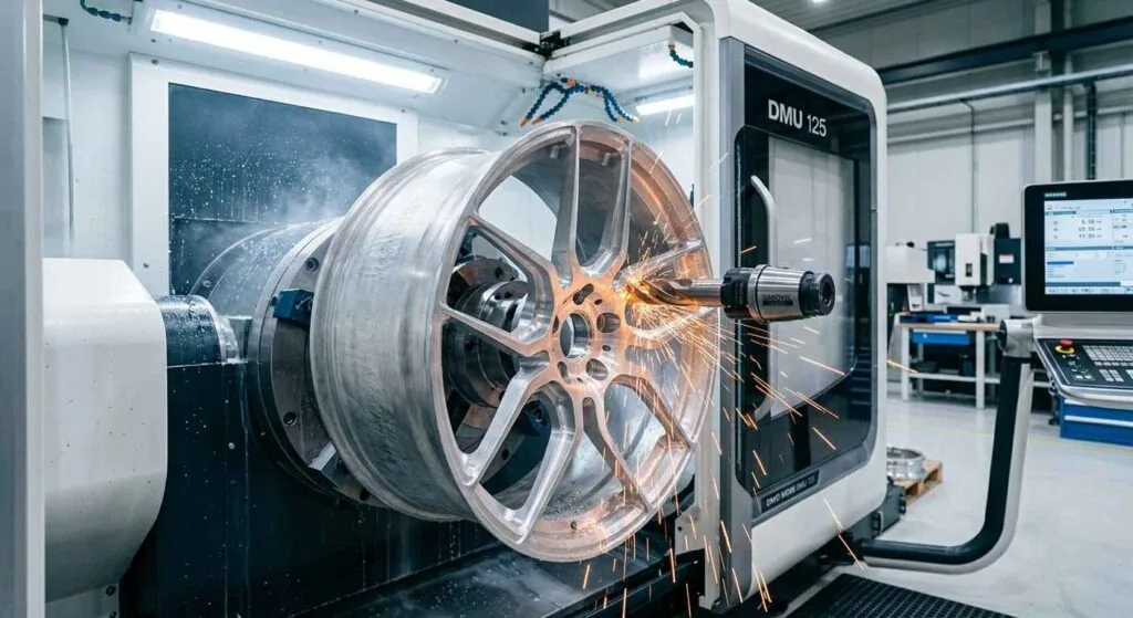
A forged wheel face is machined in a fixed sequence: the blank is inspected and fixtured on its bolt-pattern and center-bore datums, the barrel and back face are rough-turned to establish diameter, width and offset, the spoke pattern and face profile are milled, the hub bore and bolt circle are finish-bored, the surface is deburred and finished, and the part is verified on a coordinate measuring machine against the CAD model. Each stage hands a datum to the next, so an error early in the sequence propagates.
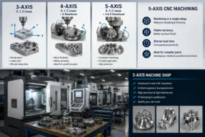
Deep concave faces, directional spokes and asymmetric designs are normally cut on multi-axis machining centres so the tool can reach undercut spoke walls without a second fixturing. Symmetric, shallow-face designs can run on 3-axis equipment at a lower machine hour rate. The deciding factor is not prestige — it is whether the geometry forces a re-fixture, because every re-fixture adds a positional error stack that lands directly on runout. Which automotive part families justify the rotary axes across a whole vehicle programme is set out in our note on 3, 4 and 5-axis machining for complex automotive parts.
| Operation | Machine | Features produced | What the operation controls |
|---|---|---|---|
| Blank inspection and fixturing | Fixture plate and gauge | Datums on bolt pattern and center bore | Every downstream dimension |
| Rough turning, barrel and back face | CNC turning services | Diameter, width, offset | Stock removal, wall thickness |
| Face profile milling | 3-axis or 5-axis CNC milling services | Spokes, concavity, lip step | Appearance, unsprung mass |
| Hub bore and bolt circle finishing | Boring head or milling centre | Center bore, bolt holes, chamfers | Hub-centric fit, vibration |
| Deburr and surface finishing | Manual and automated finishing | Edge condition, Ra target | Coating adhesion |
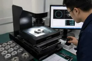
| Dimensional verification | Coordinate measuring machine | Inspection report against CAD | Acceptance, traceability |
Why fixturing is the stage that decides the programme
The fixture must hold the wheel on the datums the drawing calls out. If it references a surface the drawing does not control, the CMM report and the vehicle will disagree, and that will not surface until fitment trials.
Which tolerances actually matter on a wheel face?
On a wheel face, the tolerances that matter are the hub bore diameter, the bolt circle diameter and hole position, the mounting face flatness, and radial and lateral runout. These control whether the wheel seats concentrically on the hub and runs without vibration. Cosmetic spoke surfaces carry no functional consequence, and specifying them tightly only adds cost.
Do not specify a wheel face with one blanket tolerance. Call out the functional features individually with a datum scheme under ASME Y14.5 or ISO 1101, and let everything else default to a general class.
| Feature class | MW+ achievable tolerance (mm) | Governing reference | What drifts if it is wrong |
|---|---|---|---|
| General machined dimensions | ±0.01 | ISO 2768-m general class | Assembly fit, step alignment |
| Precision functional features | ±0.005 | Called out per feature on the drawing | Bolt seating, lip transition |
| Critical features | ±0.001 | Called out per feature, verified on CMM | Hub interface concentricity |
| Center hub bore | Per fit class on drawing | ISO 286 shaft and hole fits | Hub-centric seating, vibration at speed |
| Surface texture, as-machined to polished | Ra 3.2µm → 0.4µm → 0.1µm | ISO 4287:1997, superseded by ISO 21920-2:2021 | Coating adhesion, appearance |
MW+ runs to a process capability of Cpk ≥1.67 on controlled characteristics, which is what allows a tolerance to be held across a lot rather than demonstrated once on a sample. Mark capability-critical characteristics on the drawing so they enter the control plan. The CNC machining quality control process covers how they are captured and reported.
Worked example: bolt-circle position and hub-bore fit
Step 1, convert the bolt-hole callout. A drawing giving each bolt hole as plus or minus 0.05 mm in X and Y describes a square tolerance zone 0.1 mm on a side. The true-position diameter containing the same worst-case corner is the diagonal of that square: the square root of 0.02 = 0.141 mm. Calling out a position of 0.141 mm diameter to the centre-bore datum permits every location the coordinate form allowed, plus the round zone the feature actually needs, which is about 57 per cent more usable area at no cost to fitment.
Step 2, check the hub-bore fit. Take a 66.6 mm hub bore specified H7 against a hub spigot at h6. At the 50 to 80 mm size step, ISO 286-2 gives IT7 as 30 microns and IT6 as 19 microns, so the bore runs 66.600 to 66.630 mm and the spigot 66.581 to 66.600 mm. Maximum clearance is 66.630 minus 66.581 = 0.049 mm; minimum clearance is 66.600 minus 66.600 = 0.000 mm, line to line.
Step 3, read it against the runout budget. The worst-case eccentricity the fit alone allows is half the maximum clearance, 0.0245 mm, before a single machining error is added. If the drawing limits radial runout to 0.05 mm, the fit has already spent about half the budget. That is the case for specifying the bore as a fit rather than a size: a general size class states a band but says nothing about the mating spigot, so no clearance, and therefore no eccentricity, can be computed from it.
Which aluminum alloys are used for forged wheel faces?
Forged wheel faces are machined predominantly from 6061-T6 and 6082-T6 aluminum, with 2014-T6 and 7075-T6 reserved for weight-critical competition wheels. The 6000-series alloys combine adequate strength with good corrosion resistance and forgiving machinability; the 2000 and 7000 series buy strength at the cost of corrosion resistance and machining difficulty. Alloy is a programme decision, not a substitution the machine shop should make.
The values below are nominal published properties for the alloy and temper, of the kind held in material databases such as MatWeb. When a property is load-bearing on a wheel, work from the mill certificate for the billet lot, not from a nominal table.
| Alloy and temper | Nominal tensile strength (MPa) | Nominal density (g/cm³) | Machining and programme note |
|---|---|---|---|
| Aluminum 6061-T6 | ≈310 | 2.70 | Baseline for forged performance wheels; predictable chip formation |
| Aluminum 6082-T6 | ≈340 | 2.70 | Common in European forging supply chains; stronger than 6061-T6 |
| Aluminum 2014-T6 | ≈483 | 2.80 | Motorsport use; lower corrosion resistance, so coating spec is critical |
| Aluminum 7075-T6 | ≈572 | 2.81 | Highest strength here; slower feeds, more tool changes, higher unit cost |
Alloy choice changes machining strategy as much as it changes weight. A 7075-T6 face runs at lower feed rates with sharper tooling than a 6061-T6 face of identical geometry, so a late alloy swap invalidates the cycle time the quote was built on. MW+ machines 70+ material grades; substitution trade-offs are covered in our note on alloy selection and machining limits.
Documentation an OEM wheel programme needs
An OEM wheel programme needs three layers of evidence: part-level dimensional evidence, material traceability, and wheel-level structural validation. The first two come from the machining supplier. The third does not — validation to SAE J328 is a laboratory test on finished wheels, and no machining certification substitutes for it.
MW+ is certified to ISO 9001:2015, AS9100D, ISO 13485, IATF 16949 and NADCAP. IATF 16949 is the automotive quality management standard most global OEMs require of their supply base, and it governs how MW+ runs control plans, corrective action and traceability. It is a quality management certification, not a wheel approval, and MW+ makes no claim that any wheel design has been approved or homologated. What each scheme actually audits is compared in our note on ISO 9001, AS9100 and IATF 16949.
| Evidence required | Who produces it | When MW+ supplies it |
|---|---|---|
| Certificate of conformance | MW+ | Every order |
| CMM dimensional inspection report | MW+ | Every order |
| Material certificates for the billet lot | Mill, supplied through MW+ | Every order |
| PPAP Level 3 submission | MW+ | On request, quoted per programme |
| First article inspection to AS9102 | MW+ | On request |
| Impact, radial fatigue and cornering fatigue to SAE J328 | Accredited third-party test laboratory | Not performed by MW+ |
| Regulatory homologation for the target market | Vehicle manufacturer or approval authority | Not performed by MW+ |
Traceability that survives an audit
Traceability means the finished part number traces to a billet lot and that lot to a mill certificate. Ask the supplier to show the chain on a real past job rather than describe it. Measurement traceability matters equally: gauges and CMMs should trace to national standards of the kind maintained through NIST calibration services.
How does sourcing wheel-face machining in China change a programme?
Sourcing forged wheel-face machining in China changes three things: iteration speed on prototypes, the cost structure of the machining hours, and the physical distance between your engineers and the fixture. The first two usually favour the decision and the third does not.
MW+ operates a 15,000 m² facility in Guangming, Shenzhen, founded in 2015, with 60+ machining centres and 120+ engineering and quality professionals serving 50+ countries. In practice that means a machined wheel-face prototype from an existing blank in 48-hour express or 3–5 business days standard, production in 10–15 business days, no minimum order quantity, and headroom to 1,000,000+ units.
Where the cost difference genuinely comes from
The difference on a wheel face is a machine hour rate and a fixturing rate, not a discount. A concave face with a long cycle carries large machining content, so the hour rate dominates; a shallow face that runs in minutes carries far less, and freight and duty can erase the gap. Run it on your own cycle time, using the line items in our price-per-part breakdown.
When offshore wheel-face machining is the wrong choice
Offshore machining of forged wheel faces is the wrong choice when regional content rules apply, when the wheel design is not yet frozen, or when total landed cost is dominated by freight rather than machining hours. These situations are common enough that a supplier who never names them is not being straight with you.
| Situation | Better route | Why |
|---|---|---|
| Regional content rules attached to the vehicle programme | Regional machining supplier | No quality argument overrides a contractual content rule |
| Spoke geometry still changing during styling sign-off | Local shop until frozen, then transfer | Freight time per loop outweighs the per-part saving |
| Short cycle time, low machining content, bulky part | Machine near the assembly point | Freight and duty can exceed the machining delta |
| Wheel test scope must sit with one accountable party | A supplier who owns test-lab scope contractually | MW+ machines to print and does not perform SAE J328 testing |
| Single wheel needed for a show car next week | Local rapid machining | The 48-hour express build is real; the freight leg is not compressible |
Design decisions that stall wheel-face programmes
Four decisions account for most of the delay on custom forged wheel-face programmes, and all four are made before metal is cut.
Freezing spoke geometry before the fixture review
Undercut and deeply recessed spoke forms can be difficult to clamp without distorting the face during cutting, so review the fixture concept while the spoke form is still editable. A 2mm change to a spoke root radius costs nothing during styling; after the forging die exists it is a tooling programme.
Leaving the hub bore on a general tolerance
The center bore is a functional fit, so specify it as one with an ISO 286 fit class and a datum reference. A hub bore left to a general tolerance class will pass inspection and still produce vibration complaints, because a bore that measures in tolerance can still be too loose for hub-centric seating.
Ignoring tool access in deep concave faces
A deep concave face forces smaller cutters with longer reach, lowering the material removal rate and raising cycle time and tool wear. That is a legitimate design choice, but price it from the CAD model at quotation rather than discovering it when the first lot runs long.
Skipping the machined prototype round
Going straight from CAD to production tooling removes the only cheap opportunity to find a fitment or aesthetic problem. Forging dies are expensive and slow to change; a prototype produced by CNC prototyping is neither. Send STEP or IGES geometry, take a machined part in hand, and check caliper clearance and spoke appearance in daylight before the die is cut.
Frequently asked questions
Does MW+ certify that a forged wheel is safe or road-legal?
No. MW+ machines wheel faces to the customer’s drawing and supplies dimensional and material evidence for the parts it produces. Structural validation to SAE J328 and regulatory homologation are performed by accredited test laboratories and approval authorities, and remain the responsibility of the party that owns the wheel design. MW+ makes no safety or approval claim for any wheel.
Why is my concave 5-axis wheel face quoted so much higher than the flat-face version?
A concave wheel face is quoted higher because it takes more machine hours, not because 5-axis carries a premium for its own sake. Deep concavity forces smaller cutters with longer reach, lowering the material removal rate. The offset is setup count: a face needing three or four 3-axis fixturings can often run in one 5-axis setup, removing the re-fixturing error stack that lands on runout.
Can CNC machining alone produce a forged wheel face?
No. CNC machining cuts the face, spokes, hub bore and bolt pattern, but it cannot reproduce the grain alignment that forging creates, because grain flow is a property of how the billet was deformed under pressure. A part fully machined from plate or billet is a billet wheel face, which is a legitimate product with a different material condition — it is not a forged wheel face.
What tolerance should I put on the bolt circle diameter?
Specify the bolt circle as a positional tolerance with a datum reference under ASME Y14.5 or ISO 1101 rather than as a diameter with a ± value, because what matters is where each hole sits relative to the center bore. MW+ holds precision functional features to ±0.005mm and can hold ±0.001mm on critical features, but the drawing has to say which features those are.
How quickly can MW+ produce a machined wheel-face prototype?
MW+ delivers machined prototypes in 48-hour express or 3–5 business days as standard, once a manufacturable CAD file and a stocked or supplied blank are in hand. Quotes are returned within 24 hours. If a forging die has to be built first, the die lead time governs the programme and sits outside the machining schedule entirely.
Is PPAP included in the part price?
No. PPAP Level 3 is available from MW+ on request and is quoted per programme rather than bundled into a unit price, because the submission effort scales with the number of characteristics, the study requirements and the customer’s own PPAP template. Ask for it at the RFQ stage so it appears as a visible line item instead of a change request after award.
What should I send with an RFQ for a custom wheel face?
Send 3D geometry in STEP or IGES, a 2D drawing carrying the datum scheme and functional tolerances, the alloy and temper, the finish and coating specification, the annual volume and the documentation level required. MW+ accepts STEP, IGES, DXF, DWG, SolidWorks and PDF. A missing datum scheme is the most common reason a wheel-face quote returns with assumptions attached. Send that package and request a CNC machining quote, and ask what the fixture concept would be.