A ±0.001 mm callout is a two-micrometre total zone. Everything that can move — the machine, the tool, the fixture, the workpiece, the room and the instrument that measures it — has to share those two micrometres. At that scale the limiting factors stop being the ones machinists usually argue about and become physics: thermal expansion, measurement uncertainty and the residual stress in the bar. This is what 0.001 mm machining accuracy actually demands, worked through with the numbers rather than asserted.
Key takeaways
- Two micrometres is the whole budget. Allocating a quarter of it to thermal effects and holding ±0.5 °C limits a steel feature to about 81 mm and an aluminium feature to about 42 mm. Beyond that, temperature alone breaks the tolerance.
- ±0.001 mm is therefore a small-feature specification. It is realistic on compact geometry and unrealistic across a long dimension, whatever the machine costs.
- The measurement has to be several times better than the part. Under ISO 14253-1:2017, an expanded uncertainty of 0.5 µm leaves a 1 µm conformance zone out of the 2 µm specified.
- Machine capability is proved by named tests — ISO 230-2:2014 for positioning, ISO 230-3:2020 for thermal effects, ISO 230-7:2015 for axes of rotation.
- Specifications apply at 20 °C under ISO 1:2016. A part measured warm is a different part.
- Most features specified at this band do not need it. The counter-case section says how to tell.
On this page
- The two-micrometre error budget
- Why is ±0.001 mm a small-feature specification?
- What the machine has to prove
- Can the measurement even resolve it?
- Which processes actually reach ±0.001 mm?
- Material stability and residual stress
- What changes in the workflow
- When ±0.001 mm is the wrong specification
- Frequently asked questions
The two-micrometre error budget
The useful way to approach this band is not to ask whether a machine can hold it, but to write down the contributors and give each one a share. Contributions that are independent combine as a root-sum-square rather than by simple addition, so the budget is less brutal than it first appears — but only if no single term dominates.
| Contributor | Illustrative share of a 2 µm zone | What controls it |
|---|---|---|
| Machine positioning and repeatability | 0.5 µm | Axis accuracy and repeatability per ISO 230-2; compensation tables kept current |
| Thermal growth of the workpiece | 0.5 µm | Room and coolant temperature; feature length; material |
| Tool deflection and wear within the batch | 0.4 µm | Tool stiffness, depth of cut, offset correction interval |
| Fixturing and clamping distortion | 0.4 µm | Clamp force and location; part stiffness; release of residual stress |
| Measurement uncertainty | 0.5 µm | Instrument capability, thermal soak, operator method |
Two things follow immediately. The arithmetic only works if every term is held near half a micrometre, so a single uncontrolled contributor — a warm room, a worn tool, an over-clamped part — consumes the budget on its own. And measurement takes as large a share as the machine does, which is why this band is a metrology problem as much as a machining one.
Why is ±0.001 mm a small-feature specification?
Because thermal growth scales with length, and the tolerance does not. Dimensional specifications apply at the 20 °C reference temperature of ISO 1:2016, and any departure from it changes the dimension by ΔL = L × α × ΔT.
Worked example: the longest feature that survives ±0.5 °C
Allocate a quarter of the 2 µm zone — 0.5 µm, or 0.0005 mm — to thermal effects, and assume the part is held within 0.5 °C of reference. Rearranging gives the maximum feature length:
Lmax = 0.0005 mm / (α × 0.5 K)
| Material | Expansion coefficient (µm/m per K) | Growth per °C on a 50 mm feature | Longest feature within a 0.5 µm thermal share at ±0.5 °C |
|---|---|---|---|
| Aluminium 6061-T6 | about 23.6 | 1.18 µm | about 42 mm |
| Stainless 304 | about 17.3 | 0.87 µm | about 58 mm |
| Alloy steel 4140 | about 12.3 | 0.62 µm | about 81 mm |
| Ti-6Al-4V | about 8.6 | 0.43 µm | about 116 mm |
A 50 mm aluminium feature moves 1.18 µm per degree, which is more than half the entire zone. Tighten the environment to ±0.1 °C and the permissible length rises fivefold; loosen it to ±2 °C and an aluminium feature of about 10 mm is already at the limit.
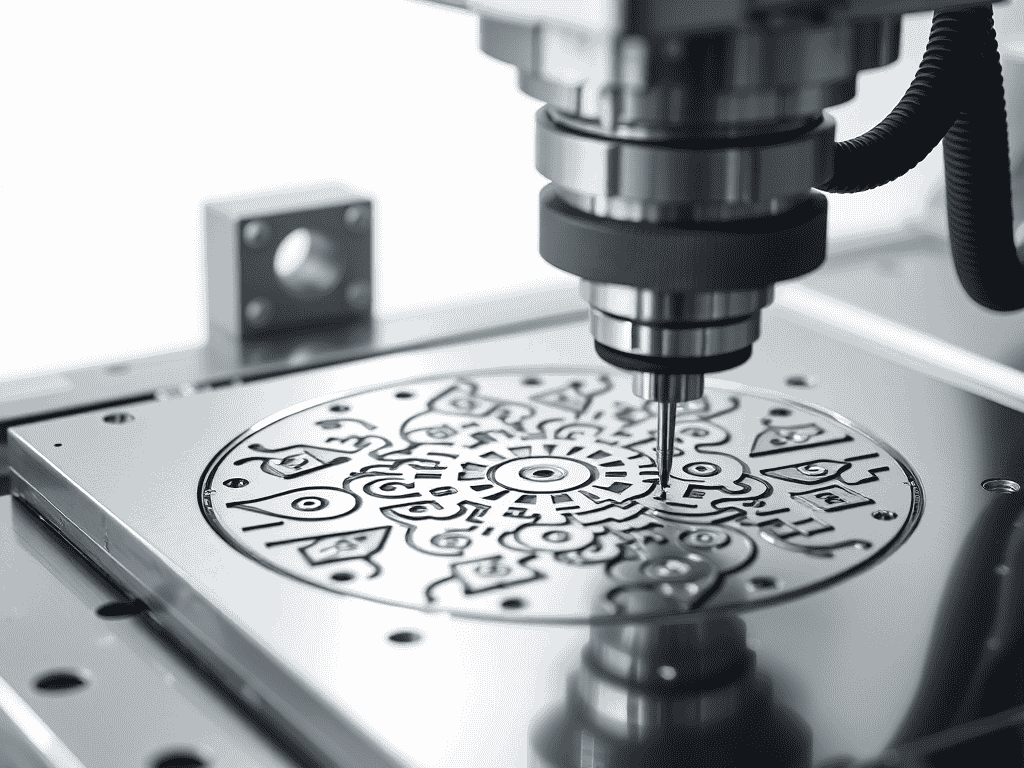
This is the honest reason ±0.001 mm belongs to small parts and short features. It is not that large machines are less capable; it is that a long dimension in an ordinary workshop cannot stay inside two micrometres while the room drifts. Work at this band therefore concentrates in micro machining services, in small precision turned and ground components, and in short features on otherwise larger parts — and the specification should say which features, not blanket the drawing.
What the machine has to prove
Machine capability at this level is not a marketing figure; it is the output of published tests, and a supplier should be able to produce the results for the specific machine that will run the job.
| Test standard | What it establishes | Why it matters at 2 µm |
|---|---|---|
| ISO 230-1:2012 | Geometric accuracy under no-load or quasi-static conditions | Squareness and straightness errors appear directly in the part |
| ISO 230-2:2014 | Accuracy and repeatability of positioning of NC axes | Repeatability, not accuracy, is what compensation cannot fix |
| ISO 230-3:2020 | Determination of thermal effects, including environmental variation error and spindle drift | The single largest uncontrolled term in most shops |
| ISO 230-7:2015 | Geometric accuracy of axes of rotation | Spindle and rotary error motions transfer straight into roundness |
| ISO 10791-7:2020 | Accuracy of finished test pieces for machining centres | Proves the whole chain, not the axes in isolation |
The distinction worth insisting on is between accuracy and repeatability. A systematic positioning error can be measured and compensated in the control; a non-repeatable one cannot, because there is nothing stable to correct. At a two-micrometre zone the repeatability figure is the one that decides whether the job is possible, and the finished test piece of ISO 10791-7 is what proves the compensation actually works under cutting conditions.
Can the measurement even resolve it?
Frequently not, and this is where ±0.001 mm programmes most often fail commercially rather than technically.
Worked example: what the instrument leaves you
Under the default decision rule of ISO 14253-1:2017, the specification zone is reduced at each end by the expanded measurement uncertainty before conformity can be declared.
Conformance zone = T − 2U. With T = 0.002 mm and U = 0.0005 mm: 0.002 − 0.001 = 0.001 mm
The part must measure within ±0.0005 mm to be proven conforming — half the drawn tolerance. Push the uncertainty to 0.001 mm and the conformance zone vanishes entirely: no part can be proven good, whatever it actually measures.
| Expanded uncertainty U | Conformance zone (T − 2U) | Effective limit on the part | Usable? |
|---|---|---|---|
| 0.0002 mm | 0.0016 mm | ±0.0008 mm | Yes — 80 per cent of the zone remains |
| 0.0005 mm | 0.0010 mm | ±0.0005 mm | Workable, with process centring |
| 0.0008 mm | 0.0004 mm | ±0.0002 mm | Marginal — most good parts fail proof |
| 0.0010 mm | 0 | — | No — conformity cannot be demonstrated |
Three practical requirements follow. The instrument’s uncertainty must be stated for the measurement being made, not quoted from a brochure. The part must reach thermal equilibrium with the metrology room before measurement, which takes longer than most schedules allow. And the decision rule should be agreed in writing, because at this band the guard band is a large fraction of the tolerance and both parties carry risk either way. This is the substance of CNC machining quality control at micron level: the argument is settled before the first part is cut, not after.
Which processes actually reach ±0.001 mm?
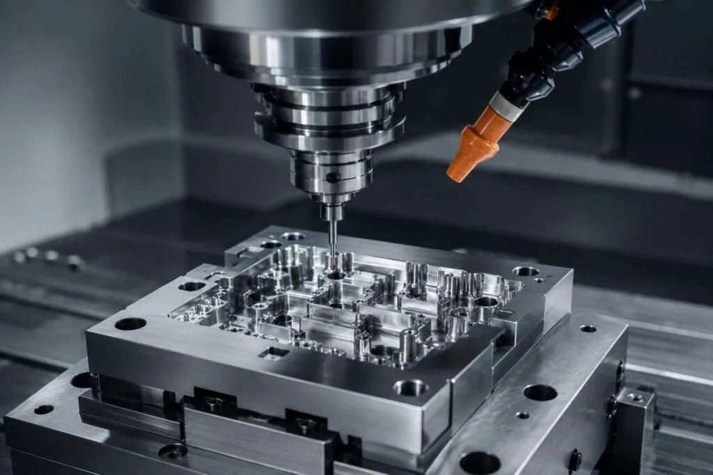
Milling and turning reach ±0.001 mm on short features under controlled conditions, but they are not always the efficient route, and on some geometry they are not a route at all.
| Process | Typical role at this band | Where it stops |
|---|---|---|
| Precision milling | Short features, small pockets, flats on compact parts | Long dimensions, deep unsupported features, thin walls |
| Precision turning and Swiss machining | Small-diameter shafts and pins, features close to the guide bushing | Long slender work without support; large diameters |
| Grinding and honing | Hardened materials, bores and cylindrical surfaces, best form control | Complex three-dimensional geometry |
| Wire EDM services | Hardened tool steels, sharp internal corners, thin sections with no cutting force | Conductive materials only; surface integrity needs attention |
| Lapping and polishing | Final size and form correction, and surface texture | Not a route to location or position |
Two notes on the table. Wire EDM is often the right answer where cutting force is the problem rather than positioning — a thin section that deflects away from a milling cutter does not deflect away from a wire. And where the requirement is really form rather than size, grinding or honing achieves it far more directly than any amount of care in a milling pass. MW+ holds ±0.001 mm where a feature genuinely requires it, alongside a general standard of ±0.01 mm to ISO 2768-m, and a process capability of Cpk ≥1.67 on controlled characteristics.
Material stability and residual stress
The bar arrives with stress in it from rolling, drawing, extrusion or heat treatment. Machining removes material asymmetrically, the remaining stress re-balances, and the part moves. At ordinary tolerances that movement is invisible; at two micrometres it is often the largest single error.
Three consequences shape how the work is planned. Roughing and finishing separate into different operations, with time between them for the part to settle, and sometimes a stress-relief step in the middle. Stock allowance for the finishing pass is set by how much movement is expected rather than by cutting efficiency. And symmetry in the material-removal sequence is worth designing for, because a part machined evenly on both sides moves far less than one hollowed out from one face.
Material choice interacts with all of this. Alloys that are dimensionally stable and cut cleanly — hardened steels, many stainless grades, titanium alloys — are the easier cases at this band. Aluminium is the common trap: it machines beautifully and is the least thermally stable of the common metals, so a part that cuts easily can still be impossible to hold in a room that drifts. The comparison in the sibling article on what ±0.005 mm means in production covers the band one step wider, where these effects are present but not yet dominant.
What changes in the workflow
Inspection moves into the process
Final inspection at this band cannot recover a batch, because by the time drift is visible the parts are made. The economic route is measurement early enough to correct the offset, which requires a fixture that presents the part identically every time and a probing routine that is itself stable to a fraction of a micrometre.
Tool life becomes a scheduled variable
A finishing tool wearing by a micrometre across a batch consumes half the zone. Control means a tool-change interval chosen so that wear across the interval stays inside its share of the budget, or in-process correction that tracks it. Either is a deliberate decision made before the batch starts.
Documentation becomes part of the deliverable
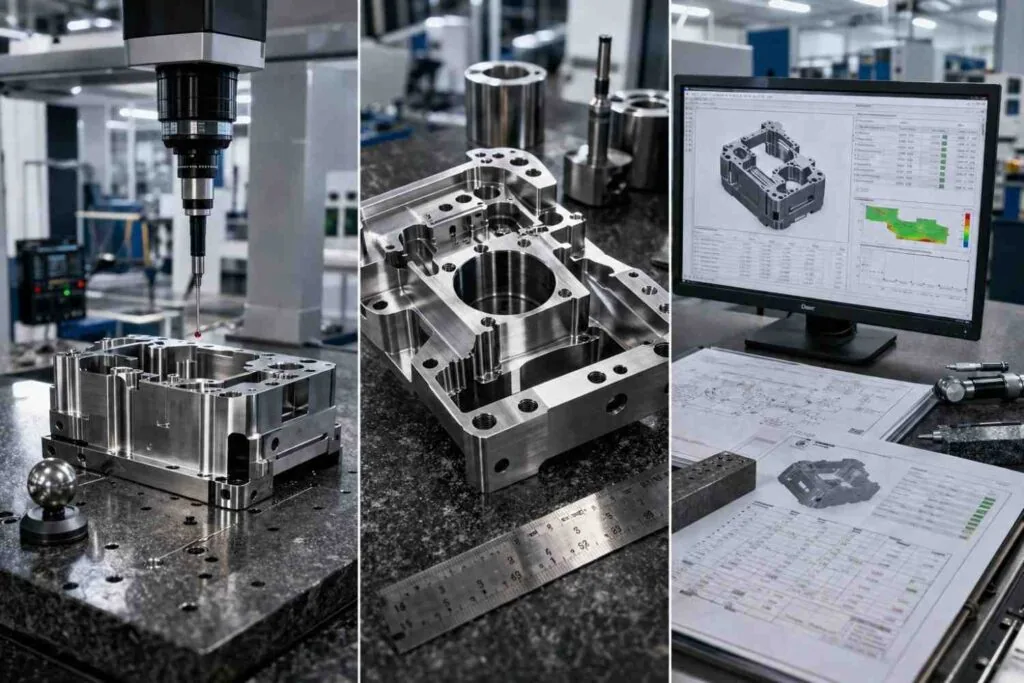
At this band a pass or fail flag is not evidence. The report needs measured values, the instrument and its stated uncertainty, the measurement temperature or a statement of equilibrium, and capability data across the batch rather than a single first article. Every MW+ order ships with a certificate of conformance, a CMM inspection report and material certificates, with first article inspection to AS9102 or PPAP Level 3 quoted per programme, under ISO 9001:2015, AS9100D, ISO 13485, IATF 16949 and NADCAP approvals.
When ±0.001 mm is the wrong specification
This band is the tightest MW+ quotes, and most drawings that carry it should not. Four tests will settle it.
The dimension is longer than the thermal budget allows
As the worked example shows, a 150 mm aluminium feature cannot hold two micrometres in any ordinary environment. Specifying it produces a part that measures differently in the morning and the afternoon, and a dispute that no inspection report can resolve. Either the environment changes or the tolerance does.
Form or position is the real requirement
Roundness, cylindricity, flatness and true position are frequently what the function depends on, and tightening a size tolerance is an indirect and expensive substitute. Controlling the right characteristic under ISO 1101:2017 or ASME Y14.5-2018 is cheaper and more effective.
The assembly absorbs more than the tolerance
Where a joint is bolted, bonded or adjusted on assembly, two micrometres of part accuracy disappears into the assembly method. The right question is what the assembled stack must hold, not what each component could hold in isolation.
The measurement chain cannot support it
If the available instrument’s uncertainty is a large fraction of the zone, the conformance band collapses and conforming parts cannot be proven conforming. Widening to ±0.005 mm frequently restores a workable margin at no functional cost; the comparison of ±0.01 mm against ±0.005 mm is a useful starting point, and the guidance on choosing a tight-tolerance vendor covers what to verify before placing the work.
±0.001 mm machining accuracy: frequently asked questions
Is ±0.001 mm the same as a machine with one-micrometre positioning?
No, and the confusion is expensive. A machine specification describes the machine under a defined test, usually ISO 230-2, with no workpiece, no cutting force and a controlled thermal state. The part’s result is the combination of the machine, the fixture, the tool, the material and the measurement. A machine quoted at one micrometre has already spent half of a two-micrometre zone before anything is cut.
Do I need a temperature-controlled room, or is a stable shop enough?
It depends on the feature length and material, which is what the worked example is for. Short features in low-expansion materials survive a stable but uncontrolled shop; long features in aluminium do not. Rather than asking for a specification of the room, state the feature length and the material and ask what temperature stability the supplier will hold during cutting and during measurement — those may be different rooms and both matter.
How long does a part need to soak before inspection?
Long enough for the whole part to reach the metrology room temperature, which depends on mass, material and how far it started from equilibrium. Small components settle quickly; a substantial steel part coming off a machine warm can take hours. The practical test is to measure, wait, and measure again: if the reading has moved, it was not soaked.
Can ±0.001 mm be held across a production run, or only on a first article?
Across a run, provided the process is centred and monitored rather than inspected at the end. That means in-process measurement, offset correction and a tool-change interval set by wear rather than by convenience. A first article at this band proves the setup, not the process; capability data across the batch is what proves the run.
Which is harder, a ±0.001 mm bore or a ±0.001 mm outside diameter?
Usually the bore, for two reasons. Internal tools are less stiff than external ones at the same reach, so deflection is larger and harder to predict. And internal measurement is generally less certain than external measurement, so the conformance zone shrinks further. Where the design allows the critical fit to sit on an outside diameter, it is worth taking.
Does surface finish have to be specified separately at this band?
Yes, and it usually determines the final process. A texture requirement is defined by ISO 21920-2:2021 (superseding ISO 4287), with sampling and filtering under ISO 21920-3:2021 (superseding ISO 4288) and drawing indication under ISO 21920-1:2021 (superseding ISO 1302). Because both conventions are still in circulation, state which governs. MW+ produces Ra 3.2 µm as-machined, Ra 0.4 µm fine-machined and Ra 0.1 µm polished.
How should an RFQ at this band be written?
Identify the specific features that need ±0.001 mm rather than applying it to the drawing, give the material and the feature length so the thermal budget can be checked, state the datum scheme, name the decision rule and reference temperature, and say what evidence the inspection report must carry.
MW+ quotes from STEP, IGES, DXF, DWG, SolidWorks and PDF files and returns a quotation within 24 hours; you can request a CNC machining quote with the drawing attached. Where the review shows a wider band would serve, that is what the reply will say — and for most work, CNC precision parts at ±0.005 mm or ±0.01 mm are the better engineering answer. The related guide on tolerance standards for precision machined parts covers how to express that on the drawing.