Reliable O-ring groove design starts by defining the seal configuration, pressure direction, O-ring size and compound, then checking squeeze, gland fill and extrusion clearance at the worst tolerance limits. A groove copied from a generic chart can be wrong when the application changes from an axial face seal to a radial piston seal, when the pressure reverses, or when heat and fluid exposure change the elastomer. Parker separates industrial static male/female glands from face-seal glands, while ISO 3601-2:2025 defines housing dimensions for general industrial O-rings within its stated scope. [1] [2]
This application guide works through a hypothetical static axial face seal. It is not an MW+ customer project, validated production design, test result or capability claim. The O-ring dimensions, tolerances and groove dimensions are teaching inputs. A released design must use the selected seal manufacturer’s current table or calculator, the actual compound and size, the governing standard, and application-specific validation.
Contents
What does an O-ring groove need to control?
An O-ring seals when the assembled hardware deforms the elastomer and pressure acts on the seal within a controlled gland. The designer therefore needs to control the groove depth, width, diameter or radial position, mating gap, edge condition and surface finish as one system. Apple Rubber distinguishes groove depth from assembled gland depth and notes that the O-ring cross-section must exceed the gland depth to create squeeze. [3]
The practical design question is not “what groove should I machine?” It is “what range of deformation and free volume will exist after every permitted O-ring and hardware tolerance is combined?” Apple Rubber’s tolerance-stack example shows why individual part tolerances must be combined: cross-section, groove and mating-hardware variation can materially change compression. [4]
Face, radial and dynamic glands are not interchangeable
| Configuration | Primary deformation | Critical definition | Design implication |
|---|---|---|---|
| Static axial face seal | Axial squeeze between two faces | Pressure direction and whether the groove ID or OD locates the ring | Use face-seal guidance and control the sealing-face gap. |
| Static radial piston seal | Radial squeeze between piston groove and bore | Piston diameter, bore diameter and radial extrusion gap | O-ring stretch and diametral tolerances enter the stack. |
| Static radial rod seal | Radial squeeze between housing groove and rod | Rod diameter, housing diameter and gap | Compression or fit of the ring in the housing must be evaluated. |
| Dynamic reciprocating or rotary seal | Controlled radial deformation with motion | Speed, lubrication, friction, wear and pressure history | Do not reuse a static gland without dynamic-seal analysis. |
ISO 3601-2:2025 covers Class A housing dimensions for general industrial O-rings and Class B dimensions intended for selected metric hardware. It also recognizes both approaches: choosing the O-ring first and designing the housing around it, or starting from fixed hardware and selecting a compatible ring. The ISO record states that special applications may require agreement between manufacturer and user. [2]
Define these inputs before choosing O-ring gland dimensions
- Seal configuration: axial face, radial piston, radial rod or dynamic.
- Pressure direction and range: including whether pressure reverses, pulses or can become trapped.
- Fluid and cleaning exposure: the selected compound must be compatible with every relevant medium.
- Temperature range: for the elastomer and both pieces of hardware, not only ambient temperature.
- O-ring designation: nominal inside diameter, cross-section, compound and applicable dimensional standard.
- Hardware materials and tolerances: groove, mating face, bore or shaft dimensions at assembly and operation.
- Motion and service life: static and dynamic glands use different design priorities.
- Assembly path: threads, ports and sharp edges can damage a ring during installation.
- Validation method: leak test, pressure proof, thermal cycling or other checks defined by the application owner.
Parker’s online O-Ring Selector supports radial piston, radial rod and axial configurations and can calculate dimensions and tolerances while considering inputs such as thermal expansion and swell. That makes it useful as a verification tool after the system inputs are known, not as a substitute for defining them. [6]
How to calculate O-ring squeeze
For the simplified static face-seal model used here, axial squeeze is:
Squeeze (%) = (O-ring cross-section − assembled gland depth) ÷ O-ring cross-section × 100
The formula is simple, but its inputs must be tolerance limits. The minimum squeeze occurs with the smallest permitted O-ring cross-section and deepest permitted gland. The maximum occurs with the largest cross-section and shallowest gland. This limit-based approach follows the tolerance-stack principle described by Apple Rubber. [4]
Apple Rubber presents a broad general starting guideline of approximately 10% to 40% squeeze for static seals and no more than 30% for dynamic seals. Those figures are not universal acceptance limits. Seal type, compound, pressure, temperature, size and manufacturer guidance can narrow the permitted window, so a released design should be checked against the selected supplier’s current data. [5]
Check gland fill, not only squeeze
A squeezed O-ring needs unoccupied gland volume for dimensional variation, thermal effects and fluid-induced volume change. Apple Rubber advises considering the minimum gland void and the maximum O-ring volume at worst case, with a general guideline that O-ring volume should not exceed 90% of the minimum gland void. It also notes that at least 75% of the seal cross-section should be contained in the groove as a general rule. These are screening guidelines; the selected seal supplier’s design table remains the release authority. [5]
For a rectangular cross-section approximation per unit of circumference:
O-ring area = πd² ÷ 4
Groove area = groove depth × groove width
Approximate gland fill (%) = O-ring area ÷ groove area × 100
This two-dimensional screen does not account for corner radii, ring stretch or compression, molded flash, installation lubricant, thermal expansion or chemical swell. The final calculation should use the actual gland geometry and the selected manufacturer’s method.
Worked example: a hypothetical static face seal
Illustrative inputs: nominal O-ring cross-section 3.53 mm with an assumed ±0.08 mm tolerance; groove depth 2.80 ±0.05 mm; groove width 4.80 ±0.05 mm. These values are intentionally treated as hypothetical inputs, not as a dimension series copied from ISO 3601, Parker or any other catalog. The example screens squeeze and fill only; it does not approve compound, pressure, diameter, clearance or service life.
| Check | Input condition | Calculation | Result |
|---|---|---|---|
| Nominal squeeze | d = 3.53 mm; depth = 2.80 mm | (3.53 − 2.80) ÷ 3.53 | 20.68% |
| Minimum squeeze | d = 3.45 mm; depth = 2.85 mm | (3.45 − 2.85) ÷ 3.45 | 17.39% |
| Maximum squeeze | d = 3.61 mm; depth = 2.75 mm | (3.61 − 2.75) ÷ 3.61 | 23.82% |
| Nominal fill | d = 3.53 mm; 2.80 × 4.80 mm groove | (π × 3.53² ÷ 4) ÷ 13.44 | 72.82% |
| Worst screened fill | d = 3.61 mm; 2.75 × 4.75 mm groove | (π × 3.61² ÷ 4) ÷ 13.0625 | 78.36% |
The nominal calculation alone would hide a 6.43 percentage-point squeeze window. The limit calculations show 17.39% to 23.82%. The worst screened fill is 78.36%, below Apple Rubber’s broad 90% maximum-volume guideline, but that does not validate the gland. The next review must add actual O-ring dimensional data, pressure and clearance, compound swell, temperature, corner radii and the chosen manufacturer’s table. [4] [5]
What the example proves and what it does not
It proves only that the stated arithmetic is internally consistent for a simplified rectangular gland. It does not prove leak tightness, pressure capacity, extrusion resistance, assembly durability or material compatibility. Those outcomes require the real component dimensions, material data and a validation plan.
Pressure direction determines the locating diameter
For an axial face seal, Parker advises locating the ring against the groove outside diameter when pressure acts outward, and against the groove inside diameter when pressure acts inward. Parker explains that this arrangement minimizes ring movement in the groove and the resulting wear or pumping action. The drawing should therefore identify the pressure side; specifying only groove width and depth leaves a critical design input unresolved. [1]
Parker also uses different face-groove widths for liquids and for gases or vacuum in its design chart. The handbook explains that a narrower gas/vacuum gland reduces dead volume and supports pump-down, while a wider liquid gland can provide more room for swell. Use the applicable chart rather than transferring the width from a different medium. [1]
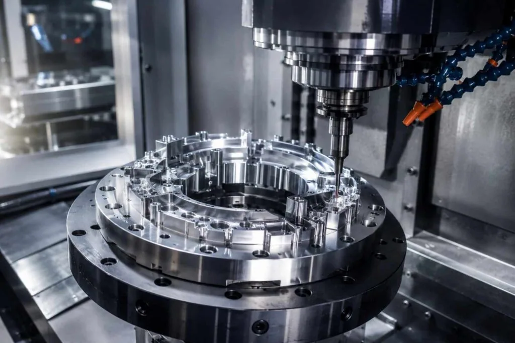
Machining access, corners and sealing surfaces
The groove drawing should control the functional surfaces without forcing an impossible sharp internal corner. Tool radius, groove width and access must be compatible, and burrs or sharp transitions on the ring’s assembly path should be removed. Apple Rubber advises keeping installation surfaces free of debris, using a compatible lubricant, preventing twist and protecting the ring from threads and sharp edges. [5]
Parker states that static sealing surfaces should generally not exceed 32 micro-inches RMS, and recommends a maximum of 16 micro-inches RMS for face-type gas seals. The handbook also warns that tool-mark direction matters because spiral or longitudinal marks can form leakage paths. These are Parker handbook values in RMS notation, not automatically equivalent drawing callouts in Ra. The drawing should state the roughness parameter, value, direction or lay where needed, and the surface to which it applies. [1]
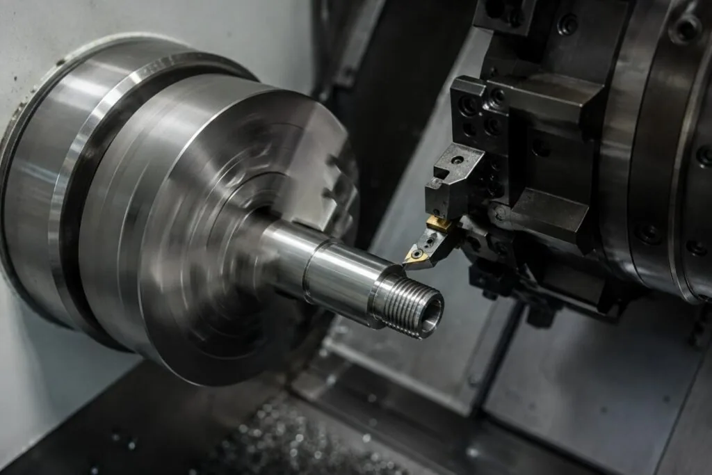
Extrusion gap, pressure, temperature and compound
Squeeze and fill are not pressure-capacity calculations. Parker’s static-seal section says that the need for back-up rings should be investigated for pressures above 103.5 bar (1500 psi), while also explaining that the decision depends on the maximum clearance gap and that fluctuating pressure can justify a back-up ring below that level. Treat 103.5 bar as a handbook investigation point, not as a universal safe limit. [1]
The engineering review should combine maximum pressure with the largest possible extrusion gap, hardware deflection, compound hardness and pressure cycling. Temperature and fluid exposure can change elastomer dimensions, while dissimilar hardware materials can change gland dimensions as temperature moves. Parker’s selector explicitly includes thermal expansion and swell among its calculation considerations. [6]
Inspection plan for a machined seal gland
| Characteristic | Why it matters | Drawing or inspection action |
|---|---|---|
| Groove depth | Direct input to axial squeeze | Dimension from the actual mating datum; report tolerance limits. |
| Groove width | Controls available gland volume | Inspect width at representative locations and account for corner radii. |
| Locating diameter | Positions a face-seal ring for the pressure direction | Identify whether ID or OD is primary and measure the functional diameter. |
| Sealing-face flatness and gap | Change assembled gland depth around the circumference | Include both parts and fastening condition in the stack. |
| Surface texture and lay | Tool marks can create leakage paths | State the parameter and applicable surface; inspect with the agreed method. |
| Edges and assembly path | Sharp edges, threads and debris can damage the ring | Specify edge treatment and inspect cleanliness before assembly. |
| Pressure/extrusion gap | Influences extrusion and back-up-ring need | Calculate at maximum clearance and operating load. |
| Validation | Dimensional conformance alone does not prove sealing | Define the application-specific leak and environmental test. |
Release checklist
- Seal configuration and pressure direction are stated.
- O-ring size, compound and governing dimensional reference are fixed.
- Minimum and maximum squeeze are calculated from tolerance limits.
- Maximum O-ring volume is compared with minimum gland volume using the supplier’s method.
- Extrusion clearance is checked at maximum pressure and hardware deflection.
- Temperature and media effects are included.
- Groove radii, edge breaks, tool access and inspection access are manufacturable.
- Surface-texture parameter and measurement method are unambiguous.
- Assembly protection and compatible lubrication are defined.
- Application-specific validation is planned.
Common O-ring groove design failure modes
Using nominal dimensions only
Nominal squeeze can look acceptable while the tolerance extremes produce too little or too much deformation. Calculate both limits and include the mating hardware. [4]
Copying a radial groove into a face seal
The deformation direction, locating diameter and pressure relationship differ. Start from the correct configuration table. [1]
Leaving no allowance for volume change
A design that consumes nearly all gland volume has little room for manufacturing variation or service-related volume change. Check worst-case fill with the selected supplier’s method. [5]
Specifying “smooth” without a roughness parameter
A numeric value without its parameter and surface scope can be interpreted incorrectly. Parker’s static values are stated in RMS, and it separately addresses tool-mark direction. [1]
Treating dimensional inspection as a leak test
Inspection can confirm the machined geometry, but sealing also depends on the selected elastomer, assembly, pressure, temperature and media. Define an application-specific validation method rather than inferring field performance from dimensions alone.
Frequently asked questions
How deep should an O-ring groove be?
There is no single universal depth. For a face seal, depth is selected to produce the required axial squeeze across the O-ring and hardware tolerances while preserving acceptable gland volume. Use the table or calculator for the exact configuration, size and compound. [1] [6]
What is the difference between groove depth and gland depth?
Groove depth is a feature of one part. Assembled gland depth is the functional distance that squeezes the seal after the mating parts are assembled; hardware gaps and mating geometry can make it different from the groove dimension alone. [3]
Should the groove ID or OD locate a face-seal O-ring?
For the Parker face-seal guidance, use the groove OD when pressure acts outward and the groove ID when pressure acts inward. If pressure reverses, the design needs a specific review rather than assuming one direction. [1]
Is an O-ring groove a good place for a default ± tolerance?
Not without checking the resulting squeeze, fill, diameter relationship and extrusion gap. Assign tolerances from the functional stack and the inspection method, then verify the limits. [4]
Does a conforming groove guarantee a leak-free seal?
No. A conforming groove is one requirement. Material compatibility, installation, mating-part geometry, pressure, temperature and validation also govern the result. Parker and Apple both treat these as system-level design factors. [1] [5]
Prepare a complete manufacturing handoff
Before requesting manufacture, send the released drawing, material specification, groove and mating-part datums, tolerance stack, roughness parameter, edge requirements, O-ring designation, pressure direction and inspection plan. For component-level discussions, review the CNC precision parts page. If rotational groove access is relevant, the CNC turning services page provides the specialist route.
For a broader technical manufacturing review, use the CNC machining services page. The MetalWorksPlus homepage is the company-level starting point. These links identify published service destinations only; this illustrative guide does not claim a verified customer project, sealing performance or production result.
Technical references
- Parker O-Ring Handbook, ORD 5700. Static glands, face-seal pressure direction, groove guidance, surface finish and extrusion considerations.
- ISO 3601-2:2025, Fluid power systems – O-rings – Part 2. Official ISO record for housing dimensions in general applications.
- Apple Rubber, Dimensional Considerations. Cross-section, gland depth and dimensional relationships.
- Apple Rubber, Tolerance Stack-Up. Worst-case hardware and seal tolerance effects.
- Apple Rubber, O-Ring Installation. General squeeze, gland-volume and installation guidance.
- Parker O-Ring Selector. Configuration-based design and material calculation tool.