Anodizing tolerance must be assessed on the finished feature, because anodic coating can shrink a bore even when the uncoated part passes inspection. In this worked case study, a hypothetical aluminum carrier needs a finished bore between 50.000 and 50.030 mm. A 40 µm hardcoat, under an explicitly assumed 50% outward-growth model, reduces the diameter by 0.040 mm.
The engineering response is to calculate the pre-finish bore from the finished requirement, account for variation, compare alternative process routes and define acceptance after treatment. An anodizing tolerance midpoint alone is not enough: a centered dimension can still fail if the coating and machining ranges consume the available tolerance.
Case status: This is an illustrative engineering study, not a completed customer project. Part geometry, alloy, dimensions, coating values and measurement allowances are design assumptions chosen to explain the method. Calculated ranges are not inspection results, and no production yield, customer approval, savings or delivery claim is made. Images from MW+’s existing media are illustrative and do not document this hypothetical part.
Contents
- The part and finished requirement
- The anodizing tolerance growth model
- Anodizing tolerance: nominal and worst-case calculation
- Growth-factor and pretreatment sensitivity
- Comparing three manufacturing routes
- The anodizing tolerance process and inspection plan
- Calculated outcome and release conditions
- FAQs and buyer checklist
Anodizing tolerance case brief: a precision bushing carrier
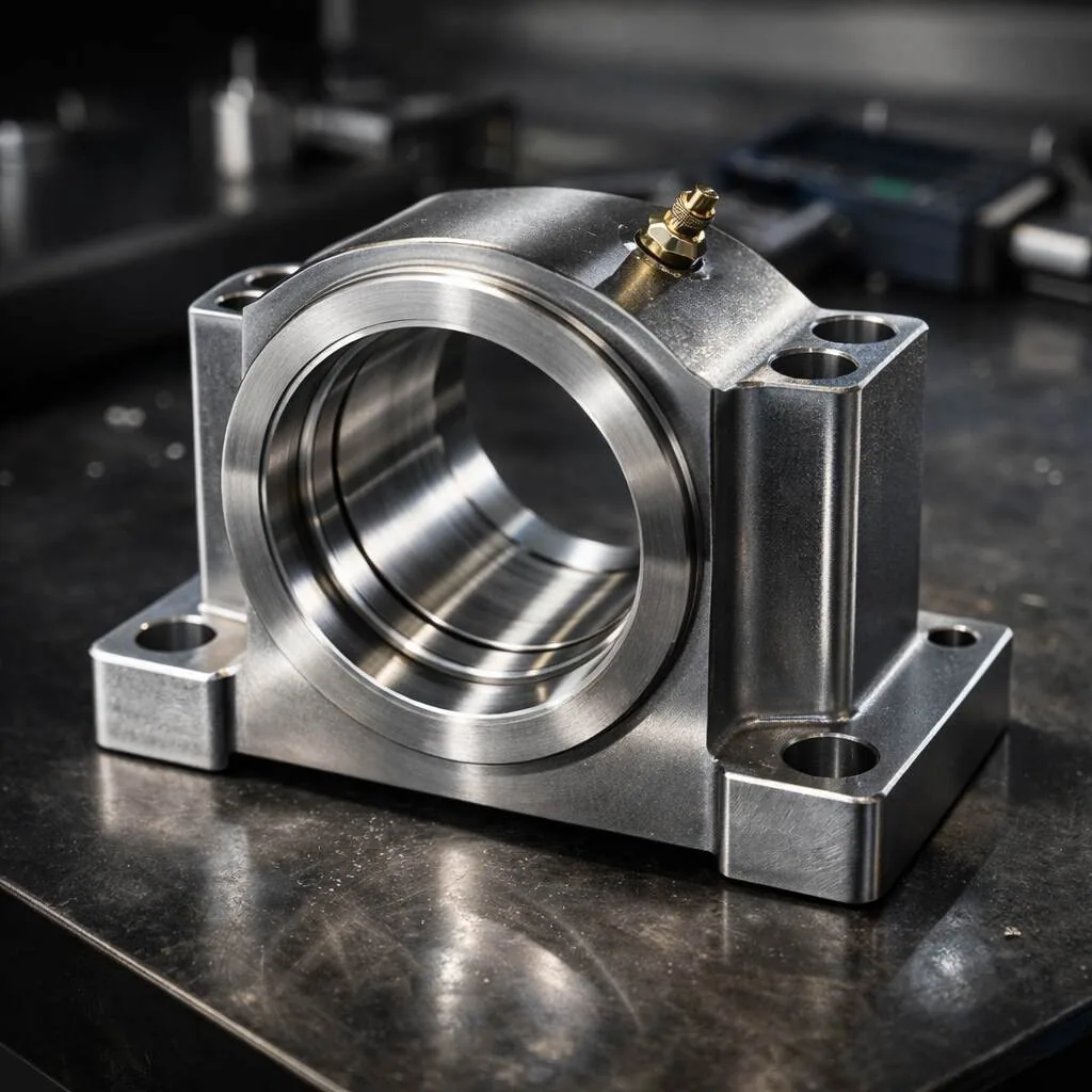
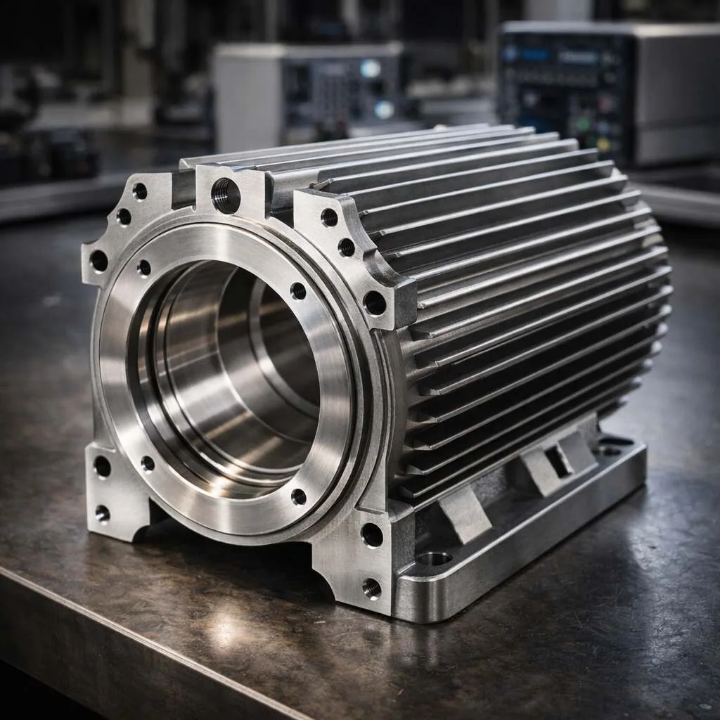
The hypothetical component is a CNC-machined 6061-T6 aluminum carrier with a cylindrical bore, mounting holes and an external flange. The bore receives a replaceable bushing. Its wear surface is intended to remain anodized, so simply removing the coating from the finished bore would not meet the assumed design intent.
The anodizing tolerance study isolates dimensional feasibility. It does not establish that this alloy, fit, coating thickness or bushing arrangement is suitable for a particular load, temperature or duty cycle. The product engineer must validate those requirements separately. This distinction matters: a dimensionally acceptable part is not automatically a functionally qualified assembly.
| Design item | Assumed requirement | Consequence for manufacturing |
|---|---|---|
| Material | 6061-T6 aluminum, machined from stock | Alloy and temper remain controlled through quotation and release |
| Finished bore | Ø50.000 to Ø50.030 mm | Acceptance occurs after the specified finishing sequence |
| Bore coating | Type III hardcoat, 40 ±5 µm total local thickness | Dimensional allowance must include coating variation |
| Growth assumption | 50% of local coating thickness grows into the bore | Diameter changes at both opposing bore surfaces |
| Pretreatment | Zero net dimensional removal in the initial calculation | Actual removal must later be measured or included in the model |
| Initial machining band | Ø50.050 to Ø50.060 mm | Provides a 10 µm pre-finish range for the worked calculation |
| Acceptance conditions | Completed finishing sequence and agreed measurement procedure | A pre-anodize dimensional report cannot substitute for final inspection |
The hardcoat thickness in this anodizing tolerance example is a case assumption, not a blanket recommendation. Confirm the process designation, class, seal condition and applicable specification revision with the product owner and finisher. Those choices influence the coating’s intended properties and the route needed to achieve them.
Why coating thickness is not the same as dimensional growth
Anodizing converts the surface rather than depositing an entirely separate layer above it. The Aluminum Anodizers Council FAQ describes approximate growth ratios and notes that alloy, process conditions and pretreatment affect dimensional change. Its hardcoat rule of thumb is approximately half inward and half outward. The Type II rule of thumb is different, so the hardcoat allowance must not be transferred automatically to another process.
For this anodizing tolerance study, use g = 0.50, where g is the fraction of total coating thickness growing beyond the metal surface immediately before anodizing. With local coating thickness t, each bore wall advances into the opening by g × t. Because a diameter spans two walls, the modeled reduction is 2 × g × t.
Without pretreatment removal: Dfinished = Dmachined − 2gt.
All dimensions in this equation must use the same units. A 40 µm coating is 0.040 mm, not 0.40 mm. At g = 0.50, the diametral reduction equals the total coating thickness numerically; it does not equal twice the total thickness.
| Feature | Modeled dimensional change | Direction of allowance |
|---|---|---|
| Internal bore | Diameter decreases by 2gt | Machine larger before treatment |
| External shaft | Diameter increases by 2gt | Machine smaller before treatment |
| Slot with two coated walls | Opening decreases by approximately 2gt | Allow extra opening where the growth model applies |
| One coated planar surface | Surface moves outward by approximately gt | Review the dimension’s reference surfaces |
These equations describe simplified geometry with the stated model. They do not predict coating distribution in a deep bore, edge buildup, thread behavior or changes in form. Specify local requirements at the critical feature and obtain evidence from the actual finishing process.
Anodizing tolerance calculation: start from the finished midpoint
The finished band midpoint is (50.000 + 50.030) ÷ 2 = 50.015 mm. Under the nominal coating assumption, diametral shrinkage is 2 × 0.50 × 0.040 = 0.040 mm. The nominal machining target is therefore 50.015 + 0.040 = 50.055 mm.
For the worked anodizing tolerance calculation, choose a pre-finish band of 50.050 to 50.060 mm. This places the midpoint correctly, but the important test is what happens at the extreme combinations.
| Condition | Calculation | Predicted finished bore |
|---|---|---|
| Nominal | 50.055 − (2 × 0.50 × 0.040) | 50.015 mm |
| Smallest final diameter | 50.050 − (2 × 0.50 × 0.045) | 50.005 mm |
| Largest final diameter | 50.060 − (2 × 0.50 × 0.035) | 50.025 mm |
| Predicted span | 50.025 − 50.005 | 0.020 mm, or 20 µm |
| Available finished span | 50.030 − 50.000 | 0.030 mm, or 30 µm |
The calculation leaves 5 µm from the predicted range to each drawing limit. Another way to see it is that a 10 µm machining range plus a 10 µm coating-driven diametral range consumes 20 µm of the available 30 µm.
Calculated result: the proposed bore band fits inside the finished requirement under the initial assumptions. Engineering decision: it is a candidate for validation, not authorization for production. The remaining margin must accommodate any effects omitted from the simplified model.
Why machining directly to the finished dimension fails in this model
If the uncoated bore were machined to 50.000–50.030 mm, the same coating range would predict a finished bore of 49.955–49.995 mm. Even the largest modeled result would be below the minimum drawing size. A successful pre-finish inspection would therefore provide false reassurance about the final fit; the anodizing tolerance requirement applies to the completed component.
This is the reader’s first practical check: determine whether the dimension on the drawing applies before or after finishing. If the condition is unstated, clarify it before programming. General tolerance notes do not resolve a contradiction between a finished fit and a treatment allowance.
Anodizing tolerance sensitivity: test the assumptions
Anodizing tolerance analysis becomes useful when it tests what could invalidate the attractive nominal answer. The initial 5 µm margin is small enough that growth ratio, pretreatment and local coating variation deserve explicit review.
Growth factor varies from 0.45 to 0.55
For a sensitivity exercise, keep the original machining and coating bands but let g vary from 0.45 to 0.55. These values are hypothetical bounds, not measured process data. The maximum reduction becomes 2 × 0.55 × 0.045 = 0.0495 mm. The minimum reduction becomes 2 × 0.45 × 0.035 = 0.0315 mm.
The extreme finished values are now 50.050 − 0.0495 = 50.0005 mm and 50.060 − 0.0315 = 50.0285 mm. The predicted span has widened to 28 µm. Only 0.5 µm remains at the lower limit and 1.5 µm at the upper limit.
The initial machining plan is therefore much less robust under this wider model. Do not solve this by assuming that all variables are independent and averaging their extremes away. Obtain paired dimensional and coating data, or revise the process and design requirements so the model has credible bounds.
Pretreatment removes 2 µm from each bore wall
If pretreatment removes e millimeters radially from each bore wall, the opening increases by 2e before anodizing. The simplified equation becomes Dfinished = Dmachined + 2e − 2gt. Here, coating growth is referenced to the post-pretreatment surface.
With e = 0.002 mm held constant and the original g = 0.50 model, the predicted finished range moves from 50.005–50.025 to 50.009–50.029 mm. The mean shifts upward by 4 µm, consuming most of the upper margin. If e also varies, include that range rather than applying a single offset.
Do not combine every sensitivity example as if it described one measured finishing line. They show why the assumptions need validation. For the actual order, use a coherent process model with agreed bounds or direct net dimensional-change data for the critical feature.
Include the measurement decision
As a further illustration, suppose the agreed acceptance procedure uses a 3 µm guard distance from each drawing limit. The resulting internal acceptance interval is 50.003–50.027 mm. The original predicted range fits within it; the wider growth-factor range does not.
A guard distance is a decision-rule choice, not a universal subtraction from every tolerance. Measurement uncertainty must be established for the actual method, feature and conditions. Agree the decision rule with the buyer’s quality team; do not invent an uncertainty value from an instrument’s display resolution.
Anodizing tolerance routes: compensation, masking or final cutting
There is more than one way to handle anodizing tolerance. The correct choice depends on which surfaces need protection, how the fit is used, what the finisher can control and what the product owner will approve.
| Route | Advantage | Trade-off | Suitability for this case |
|---|---|---|---|
| Compensate bore before anodizing | Retains the intended anodized bore surface | Depends on controlled net dimensional change and coating distribution | Preferred candidate if validation supports the required range |
| Mask the bore | Avoids oxide growth on the functional fit | Bare bore needs an approved corrosion/wear strategy; masking boundary can matter | Requires a change to the assumed coated-bore requirement |
| Finish-machine after anodizing | Allows final bore sizing after treatment | Removes coating from the cut surface, adds a setup and may damage adjacent finish | Requires approval because it changes surface condition |
For the stated case, retain pre-finish compensation as the validation candidate. Masking and post-finish sizing remain alternatives if the owner revises the functional requirement. Neither route is an automatic rescue for an undersize hardcoated bore.
Discuss tooling, fixture access and final bore form with the machining supplier. Our CNC milling services apply to housings and carriers; rotational components may instead suit CNC turning. The geometry determines the route, while the finished requirement determines the allowance.
Translate the anodizing tolerance calculation into a controlled plan
Drawing and finishing instructions
The product drawing should define the final required bore, its form and location requirements where needed, and the condition in which those requirements apply. Keep the machining compensation in a controlled manufacturing document unless the design owner intentionally defines separate pre-finish and post-finish requirements.
The anodizing tolerance finishing instruction should identify the alloy, treatment designation, local thickness requirement, seal condition, critical surfaces, permitted rack locations and any masking. Include how local thickness at the bore is to be verified or supported. A witness coupon can help characterize a process, but it does not automatically prove coating thickness or dimensional change inside the part.
Reference the current, contractually required edition of the coating specification. The DLA ASSIST record for MIL-PRF-8625 is an official place to identify that specification. The study’s dimensional assumptions do not replace its requirements or the buyer’s finishing specification.
Manufacturing sequence
- Review the released model, drawing and coating requirements together.
- Establish the locating features and machine the housing route without distorting the bore.
- Finish the bore to the approved pre-finish band and inspect size and form.
- Identify the lot and record the pre-finish dimensional condition.
- Apply the agreed pretreatment, anodizing and completion sequence with controlled routing.
- Inspect the final bore and related functional features under the agreed measurement procedure.
- Resolve nonconforming parts before shipment; preserve the link between dimensional and finishing records.
Do not select a machining tolerance that the route cannot reliably achieve. The 10 µm pre-finish band here is an assumption for the calculation, not a promise for every geometry. If the housing distorts after unclamping, coating allowance will not solve the form problem.
Anodizing tolerance inspection: compare the same feature before and after treatment
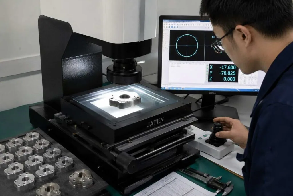
For validation, choose identifiable sample parts and record paired before/after dimensions at defined axial sections. Include more than one angular orientation where the method requires it. A single diameter reading cannot establish taper, roundness or the condition over the full engagement length.
Separate size verification from surface-property verification. A bore can have the correct diameter but an unacceptable coating or surface finish. Equally, a satisfactory coating-thickness result does not prove the final bore size. The anodizing tolerance acceptance plan should identify evidence for both requirements.
| Inspection stage | Evidence to retain | Decision supported |
|---|---|---|
| Before treatment | Actual bore measurements, lot/part identity, method and conditions | Whether machining meets the approved input band |
| During process validation | Paired net dimensional change and evidence for critical coating requirements | Whether the compensation model has credible bounds |
| After all finishing | Final bore size/form, finish evidence and agreed decision rule | Whether the finished part meets the drawing |
| Shipment release | Applicable revision, quantity reconciliation and conformity records | Whether the accepted population is the one being shipped |
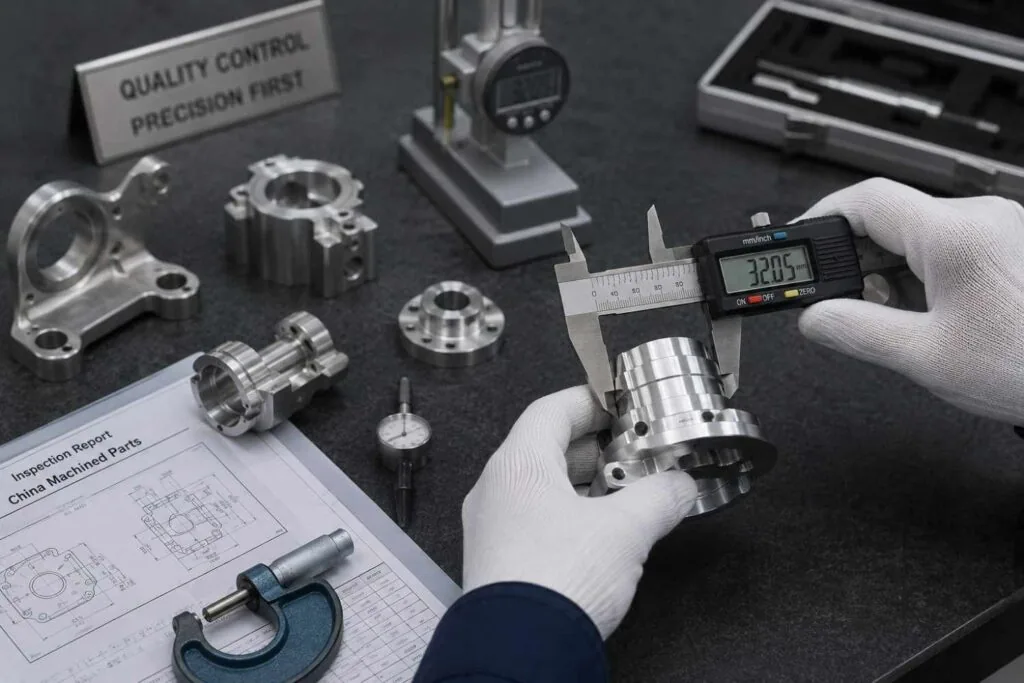
Specify an instrument and method capable of resolving the decision being made. A general-purpose caliper is not an adequate substitute for a validated precision-bore measurement method simply because it displays hundredths of a millimeter. Depending on the feature, a suitable bore gauge, air gauge or validated CMM strategy may be considered.
For understanding datum alignment and report structure, read our CMM inspection report guide. This case adds the finishing-stage question: was the feature measured in its final acceptance condition?
Calculated outcome and conditions for production release
The initial anodizing tolerance model predicts a finished bore of 50.005–50.025 mm from a pre-finish bore of 50.050–50.060 mm. That fits within the illustrative 50.000–50.030 mm requirement. The anodizing tolerance sensitivity exercises show how quickly the margin can disappear when growth ratio or pretreatment is insufficiently defined.
The recommended next step is a validation batch with paired measurement records and agreed coating verification. Release production only when the demonstrated process supports the final requirement and acceptance method. If it does not, revisit compensation, machining variation, finishing controls or the product design.
No yield or capability index can be calculated from these assumed ranges. A Cpk value requires actual process data and a suitable statistical assessment. Likewise, this study provides no basis for claiming zero defects, a percentage cost reduction or a particular turnaround time.
What would invalidate the proposed route?
- Local coating or net dimensional variation exceeds the assumed bounds.
- Bore form changes beyond the drawing requirement after treatment.
- Measurement uncertainty prevents a dependable acceptance decision.
- The coating’s functional requirements conflict with masking or subsequent cutting.
- The owner requires a tighter finished fit without approving a revised process.
These are decision points, not reasons to omit finishing from the drawing. A documented anodizing tolerance plan gives the buyer and supplier a shared basis for choosing a route. Generic wording such as “black anodize, standard tolerance” does not do that for a critical fit.
Frequently asked questions
How much does hardcoat anodizing reduce a bore?
Under the illustrative 50% outward-growth model, bore diameter reduction equals the total local coating thickness: a 40 µm coating predicts a 40 µm diameter reduction. Actual net change depends on the process, alloy and pretreatment and must be validated for the feature.
Can the same allowance be used for Type II anodizing?
No. Do not transfer this Type III calculation directly. Establish the relevant growth model or measured net dimensional change for the actual finishing process and local geometry before setting the machining target.
Should the drawing specify dimensions before or after anodizing?
Clearly identify the acceptance condition. For a final functional fit, define the finished requirement; if a pre-finish dimension is also a design requirement, identify it separately. Avoid leaving the supplier to infer which condition applies.
Is masking always the best way to preserve a tight fit?
Masking can avoid coating growth in the bore, but it leaves a different surface condition. Confirm that the bare surface meets the required wear, corrosion and assembly needs. Define the masking boundary and permitted residues.
Can an undersize anodized bore simply be reamed?
Only with an approved rework route. Reaming removes coating at the cut surface and can affect adjacent finish or geometry. The product owner must approve the changed surface condition and the required reinspection.
Does a pre-anodize CMM report prove the final bore is acceptable?
No. It proves only the inspected pre-finish condition. When acceptance applies after finishing, final size and other specified characteristics need evidence from that condition.
Anodizing tolerance checklist for a precision coated component
Send the released drawing and model, exact material, finished dimensional band, coating specification and revision, local thickness requirements, seal condition, masking map, bore function, required quantities and inspection expectations. Provide the mating-part requirements when they are necessary to evaluate the fit.
For a custom housing or carrier, review MW+’s precision parts offering and machine parts manufacturing, then request a technical quotation. Ask for the dimensional allowance and post-finish inspection basis to be addressed in the review.
Keep approved changes linked to the order. A later change in coating thickness or masking can invalidate the original compensation even when the model geometry is unchanged. Our engineering change control guide explains how to preserve the baseline across machining, finishing and inspection.
Sources and calculation scope
The linked Aluminum Anodizers Council FAQ supports the distinction between coating thickness, growth and process-dependent dimensional change. The DLA record identifies the referenced coating specification. All case inputs, route comparisons and numerical outputs above are editorial engineering analysis for an illustrative scenario. Production decisions require approved requirements and evidence from the actual machining and finishing process.