






Adding rotary axes to a milling machine does not make it more accurate. It makes it possible to hold accuracy across features that would otherwise need three or four separate setups, and that is a different claim. This page explains how 5-axis machining works: what actually changes as you move from 3-axis to 4-axis to 5-axis, what it costs, and when paying for 5-axis is the wrong decision.
Key takeaways
- The gain from 5-axis is setup elimination, not spindle accuracy. Every re-clamp introduces a fresh datum error, and those errors add across setups.
- 3+2 indexed machining locks the rotary axes before cutting and is stiffer than simultaneous motion. Use simultaneous 5-axis only when the geometry genuinely requires it.
- MW+ holds ±0.01 mm to ISO 2768-m generally, ±0.005 mm as a precision figure and ±0.001 mm on selected features, with Cpk ≥1.67 on controlled characteristics.
- A drawing without datums is not quotable on 5-axis. Reference features per ISO 1101 or ASME Y14.5 and mark which dimensions are critical.
- 5-axis is the wrong choice for prismatic plate parts, single-face work and high-volume simple geometry. A 3-axis shop will beat it on price every time.
- What changes as you add axes?
- Why does a single setup hold tolerance better?
- What does 5-axis machining actually cost?
- When is 5-axis the wrong choice?
- How do you write a drawing a 5-axis shop can quote?
- Materials, finishes and what they do to cycle time
- How MW+ runs 5-axis work
- Frequently asked questions
- What to send us
How 5-axis machining works: what changes as you add axes?
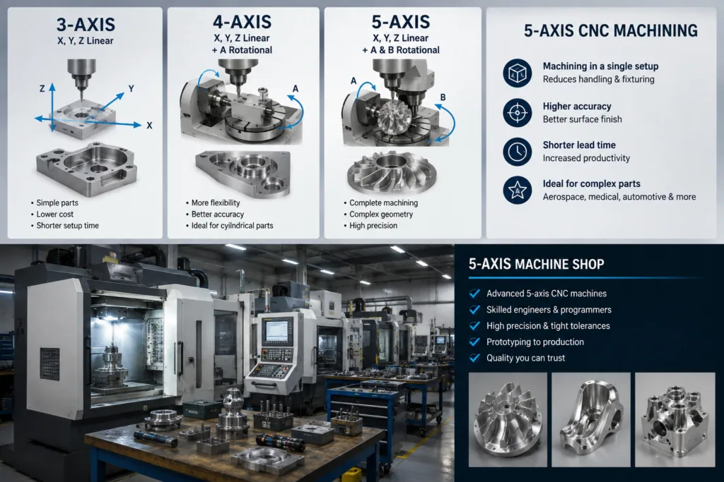
An axis is a degree of freedom between the tool and the workpiece. Adding one does not improve the machine’s positioning accuracy; it changes which surfaces the tool can reach without the part moving.
3-axis milling
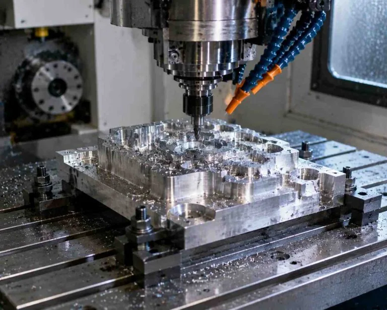
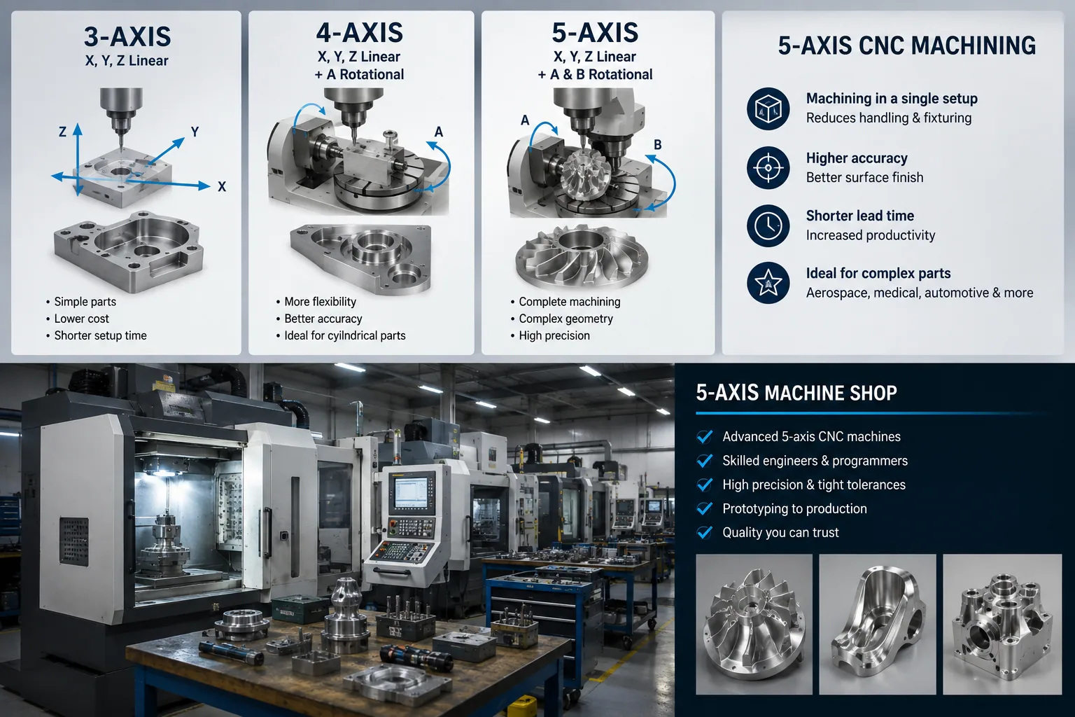
The tool moves in X, Y and Z. The part stays fixed and the spindle approaches from one direction per setup. This is efficient for flat faces, pockets, slots and prismatic parts. It struggles with compound angles, undercuts and features on multiple faces, because each additional face requires a repositioning that adds to the tolerance stack.
4-axis milling
A single rotary axis, usually A about X, is added to the linear travel. The workpiece rotates, so several sides can be machined without unclamping. It suits shafts, cylindrical bodies and parts whose features sit on planes perpendicular to the rotary axis. Freeform surfaces and features on non-orthogonal planes remain out of reach.
3+2 indexed 5-axis
Two rotary axes position the part at a compound angle, then lock. Cutting happens as conventional 3-axis motion in that orientation. This is the workhorse mode, and it is the one most buyers actually need. Locked rotaries are stiffer than moving ones, so 3+2 often produces a better finish and allows heavier cuts than continuous motion on the same machine.
Simultaneous 5-axis
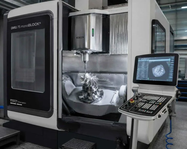
All five axes interpolate while the tool is cutting. This is what freeform surfaces require: impellers, turbine blades, blended fillets and swept contours where the tool axis must stay normal to a curved surface. It also lets a short, rigid tool reach into a deep cavity by tilting rather than by extending, which reduces deflection and chatter.
| Configuration | Motion axes | Setups for a five-face part | Best for |
|---|---|---|---|
| 3-axis | X, Y, Z | Five | Flat faces, pockets, slots, prismatic parts |
| 4-axis | X, Y, Z + 1 rotary | Two or three | Shafts and radial features on orthogonal planes |
| 5-axis, 3+2 indexed | X, Y, Z + 2 rotary, locked while cutting | One | Compound angles, multi-face brackets, housings |
| 5-axis simultaneous | X, Y, Z + 2 rotary, continuous | One | Impellers, blades, blended freeform surfaces |
Why does a single setup hold tolerance better?
Every time a part is unclamped and re-clamped, the machine has to find the datum again. Locating error, clamping distortion and probe uncertainty combine, and the new origin does not land exactly where the old one was. On a well-run shop with a probing cycle, that error is small; it is not zero.
The problem is that the errors accumulate. A feature machined in setup four is referenced to a datum that has been re-established three times. If your drawing calls out true position between a bore in setup one and a face in setup four, the achievable position is the sum of those relocations, not the machine’s positioning accuracy.
Machining all five faces in one clamping removes that entirely. Every feature references the same physical origin, so the position tolerance you can hold is governed by the machine and the toolpath rather than by fixturing. This is why multi-axis machining is specified on parts where relationships between faces matter more than any single dimension.
| Tolerance level | Typically achievable on | Typical use | Cost impact |
|---|---|---|---|
| ±0.01 mm, ISO 2768-m | General features, any configuration | Clearance holes, non-critical faces | Baseline |
| ±0.005 mm | Single-setup 5-axis, controlled temperature | Bearing bores, sealing faces, mating features | Slower feeds, in-process probing |
| ±0.001 mm | Selected features, dedicated fixturing | Press fits, optical mounts, instrument seats | Significant; quote per feature, not per part |
| Position across faces | One clamping only | Multi-face brackets, manifolds, housings | Drives the choice of 5-axis in the first place |
Tolerance is only meaningful if it is verified. Dimensional reports should come from a CMM whose calibration is traceable to a national measurement institute; NIST sets out what traceability requires, and a supplier who cannot describe their chain does not have one.
What does 5-axis machining actually cost?
The hourly rate on a simultaneous 5-axis machine is higher than on a 3-axis mill, and buyers often stop there. The comparison that matters is total cost per accepted part, which includes setups, fixtures, inspection and the parts you scrap.
| Cost driver | 3-axis route | 5-axis route | Which wins |
|---|---|---|---|
| Machine hourly rate | Lower | Higher | 3-axis |
| Setups per part | One per face | One total | 5-axis, decisively on multi-face parts |
| Fixture cost | A fixture per orientation | One fixture or a vise and tombstone | 5-axis |
| CAM programming | Simple, fast | Longer, needs collision simulation | 3-axis |
| Tooling | Longer reach, more deflection | Shorter, more rigid tools by tilting | 5-axis |
| Inspection | Per-setup verification | One inspection pass | 5-axis |
Two practical consequences. On a one-off prototype the programming time dominates, so a simple part is usually cheaper on 3-axis even if it needs three setups. On a repeat part with five machined faces, the setup saving compounds every batch and 5-axis is normally cheaper by the second order.
When is 5-axis the wrong choice?
Most of the parts we are asked to quote on 5-axis do not need it. Specifying it anyway raises your price and buys nothing. Here is where we would route you to a different process, including away from us.
| If your part is… | Use this instead | Why |
|---|---|---|
| A flat plate with features on one face | 3-axis milling, or laser cutting for the blank | Rotary axes add cost and no access |
| Prismatic with features on two opposing faces | 3-axis with a simple flip fixture | One re-clamp is cheaper than 5-axis programming |
| A turned body with a few cross-holes | Turning with live tooling, or 4-axis | The geometry is rotational, not freeform |
| Small, slender and produced in thousands | Swiss machining | Swiss turning holds slender parts far better |
| Hardened steel with sharp internal corners | Wire or sinker EDM | No cutter can produce a zero-radius corner |
| A one-off form-and-fit check | Additive, then machine only the critical faces | You are buying geometry, not tolerance |
There is also a limit on the other side. A 5-axis machine cannot reach a fully enclosed internal cavity, cannot produce internal corners sharper than the cutter radius, and struggles with thin walls below roughly 0.5 mm without dedicated support strategies. If your design depends on any of those, the answer is a design change or a different process, not a better machine.
How do you write a drawing a 5-axis shop can quote?
The single most common reason a 5-axis quote comes back slow, expensive or hedged is an ambiguous drawing. Four things fix most of it.
Declare your datums
A 5-axis part has no natural “top”. Without a datum reference frame the programmer has to guess which relationships matter, and the CMM operator has to guess how to fixture the inspection. Specify a primary, secondary and tertiary datum per ISO 1101 or ASME Y14.5, and put them on features that actually locate the part in service.
Tolerance the critical features and only those
Blanket-tightening every dimension is the most expensive habit in mechanical design. Put a general tolerance block on the drawing, typically ISO 2768-m, then call out the handful of features that genuinely need ±0.005 mm or tighter. A shop can then concentrate its process control where it changes the outcome.
State the surface finish where it matters
Surface roughness is defined in ISO 4287, and Ra alone is not always the right parameter for a sealing or bearing face. As-machined work typically lands around Ra 3.2 µm; fine machining reaches Ra 0.4 µm and polishing Ra 0.1 µm. Each step down costs time, so mark the faces that need it and leave the rest as-machined.
Send the model, not just the PDF
Toolpaths are generated from solid geometry. A STEP or IGES file plus a dimensioned PDF lets a programmer simulate collisions against the real trunnion and fixture. We accept STEP, IGES, DXF, DWG, SolidWorks and PDF, and return design-for-manufacture feedback with the quote rather than after you have committed.
Materials, finishes and what they do to cycle time
Material choice changes 5-axis cost more than geometry does. Titanium and nickel alloys run at a fraction of the surface speed of aluminum and load the tool far harder, which is exactly when the ability to tilt and keep a short tool matters.
We machine 70+ grades, including aluminum 6061 and 7075, titanium Ti-6Al-4V, stainless 304, 316 and 17-4 PH, Inconel, brass, copper and engineering plastics such as PEEK. Published values for density, tensile strength and thermal conductivity are nominal; MatWeb is a reasonable first reference, but when a property is load-bearing you should work from the actual mill certificate for the lot supplied. Every order ships with material certificates for exactly that reason.
Finishing is in-house: anodising to Type II and Type III, passivation, electropolish, hard chrome, powder coating and black oxide, processed to the relevant ASTM or AMS specification. Where a finish adds thickness, say so on the drawing and state whether the tolerance applies before or after coating. It is a common and expensive omission.
How MW+ runs 5-axis work
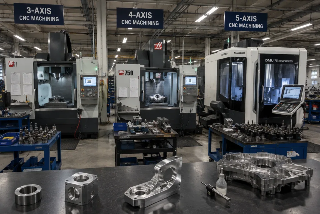
MW+ (MetalWorks Plus) was founded in 2015 and operates a 15,000 m² facility in GuangMing District, Shenzhen, with 60+ machining centres and 120+ engineers and machinists. The 5-axis cells include DMG MORI NMV and Mazak VARIAXIS machines, and the workshop is temperature-controlled so thermal growth does not eat the tolerance you paid for.
Certifications are ISO 9001:2015, AS9100D, ISO 13485, IATF 16949 and NADCAP. Process capability is held at Cpk ≥1.67 on controlled characteristics. Every order ships with a certificate of conformance, a CMM inspection report and material certificates; first article inspection to AS9102 and PPAP Level 3 are available on request and quoted per programme.
| Phase | What happens | What you get |
|---|---|---|
| DFM review | Geometry checked for 5-axis access, fixturing and collision risk | Written feedback with the quote, within 24 hours |
| CAM programming | Toolpaths built and simulated against the real machine kinematics | Confirmation of achievable tolerance per feature |
| Fixturing | One clamping wherever the geometry allows | All features on a single datum frame |
| Machining | 3+2 indexed or simultaneous, chosen per feature | Prototypes in 3–5 business days, 48-hour express available |
| Inspection | CMM verification of critical dimensions | COC, dimensional report, material certificates |
| Production | Repeat batches from the proven program | 10–15 business days, no minimum order quantity |
The same cells support CNC milling, prototyping and small-feature work through micro-machining, so a part that starts as a one-off can move to production without changing supplier or re-qualifying the process. Inspection standards are set out on our quality assurance page.
Impellers are the textbook simultaneous 5-axis part. Our impeller machining case study shows how a US aerospace OEM’s impellers were held to ±0.005mm concentricity and delivered in 4 days.
Frequently asked questions
Why is my 5-axis part quoted higher than the 3-axis equivalent?
Two reasons dominate. The machine rate is higher, and the programming takes longer because every move has to be simulated against the trunnion, fixture and tool holder to prove there is no collision. On a single prototype that programming time is not amortised, so the quote looks expensive. On a repeat part the setup saving usually reverses the comparison by the second batch. Ask for both routes to be quoted if the geometry allows it.
Do I need simultaneous 5-axis, or is 3+2 enough?
If your features sit on flat faces at compound angles, 3+2 indexed machining is enough and usually better, because locked rotary axes are stiffer and allow heavier cuts. Simultaneous motion is required when the tool axis must stay normal to a continuously curving surface, as on an impeller, a turbine blade or a blended fillet. Send the model and a programmer can tell you in a few minutes which one your part needs.
What tolerance can you actually hold on a 5-axis part?
General features run to ±0.01 mm against ISO 2768-m. Precision features are held at ±0.005 mm, and ±0.001 mm is achievable on selected features with dedicated fixturing and temperature control. What matters more on a multi-face part is position between features, which is why a single setup is specified. Send the drawing and we will confirm feature by feature rather than quoting a headline number.
How thin can a wall be on a 5-axis machined part?
Around 0.5 mm is a practical floor in aluminum with supporting strategies, and it depends heavily on wall height, material and how the part is held. Thin walls fail through deflection and vibration, not through machine accuracy, so the fix is fixturing, stepped-down cuts and sometimes sacrificial support material. Tell us the wall dimension early; it changes the fixture design, and the fixture design is quoted with the part.
Can you machine titanium and Inconel on 5-axis equipment?
Yes, and 5-axis is often the better route for them. Both alloys run at low surface speed and generate heat at the cutting edge, so keeping the tool short and rigid matters more than it does in aluminum. Tilting the part to present the surface to a short tool, rather than extending a long one into a cavity, reduces deflection and extends tool life. Expect cycle times several times longer than the aluminum equivalent.
What inspection documentation comes with the parts?
Every order ships with a certificate of conformance, a CMM inspection report covering the critical dimensions, and material certificates for the lot supplied. Full first article inspection to AS9102 and PPAP Level 3 submissions are available on request and quoted per programme, because both add real engineering hours and should not be buried in a unit price.
Is there a minimum order quantity for 5-axis work?
No. There is no minimum order quantity, and single prototypes are welcome. Be aware that programming and fixturing are largely fixed costs, so the unit price on quantity one carries all of it. If you expect to repeat the part, say so at quote stage and ask for pricing at both quantities so you can see how the fixed cost amortises.
What to send us
A STEP file, a dimensioned drawing with datums declared, the material and grade, the quantity, and a note of which two or three dimensions are genuinely critical. That is enough to return a quote and written DFM feedback within 24 hours, including a straight answer on whether the tolerance you have asked for is one we can hold.
If you are not sure whether your part needs 5-axis at all, send it anyway and say so. We would rather quote it on the cheaper process and keep the work than sell you rotary axes you do not need.
Running this work at MW+
Simultaneous 5-axis work is run on the machines described on our multi-axis CNC machining page, holding ±0.001 mm on selected features in a single setup. Typical outputs are CNC precision parts and structural machine parts — see all machined products.