A 0.005 mm tolerance written as ±0.005 mm is a 0.010 mm total zone — ten micrometres for everything: machine positioning, tool wear, workholding, thermal growth and the uncertainty of the instrument that proves the part good. Most of the difficulty at this band is not in cutting metal. It is in the fact that several unavoidable contributors each want a share of ten micrometres, and the arithmetic below shows how little is left once they have taken it.
Key takeaways
- ±0.005 mm is not one difficulty level. Against ISO 286-2:2010, a 10 µm zone sits between IT6 and IT7 on a 5 mm feature but tighter than IT5 on a 100 mm feature. Same callout, different process.
- A Cpk of 1.67 on a 0.010 mm zone means a process standard deviation of about 1 µm — and about 0.8 µm if the process sits 1 µm off centre.
- Measurement uncertainty is subtracted from the zone. Under ISO 14253-1:2017, an expanded uncertainty of 0.002 mm leaves a 0.006 mm conformance zone — the part must measure within ±0.003 mm to be proven good.
- One degree costs you real microns. A 100 mm steel feature grows about 1.2 µm per °C; the same feature in aluminium grows about 2.4 µm. Specifications apply at 20 °C under ISO 1:2016.
- Blanket ±0.005 mm is usually the wrong call. The counter-case section sets out where it costs money and buys nothing.
On this page
- What a ±0.005 mm callout actually specifies
- Why does the same ±0.005 mm get harder as the part gets bigger?
- What process capability does ±0.005 mm demand?
- Measurement uncertainty is taken out of the zone first
- Temperature: the error nobody puts on the drawing
- Which features genuinely earn ±0.005 mm
- What changes on the shop floor at this band
- What does the inspection report have to show?
- When ±0.005 mm is the wrong call
- Frequently asked questions
What a ±0.005 mm callout actually specifies
It specifies a zone, not a target. A dimension of 25.000 ±0.005 mm is conforming anywhere between 24.995 and 25.005 mm. Every part produced inside that band is equally acceptable, and a supplier holding the middle of it is not doing better work than one holding the edge — unless the drawing says so, which it usually does not.
That matters because the zone is the whole budget. Within those ten micrometres sit the machine’s positioning error, the deflection of tool and workpiece, tool wear across the batch, the repeatability of the fixture, thermal growth during the cycle, and the uncertainty of the measurement itself. None of these is optional and none can be set to zero. The practical question at this band is never “can the machine do it” but “what does each contributor get, and does the total fit”.
Note also what the callout does not say. A ±0.005 mm size tolerance says nothing about form, orientation or location. A bore can be exactly 25.003 mm at every point of measurement and still be unusable because it is bent, tapered or out of position. Those are separate controls under ISO 1101:2017 or ASME Y14.5-2018, and a drawing that tightens size without controlling form has usually not solved the problem it set out to solve.
Why does the same ±0.005 mm get harder as the part gets bigger?
Because the standard tolerance grades in ISO 286-2:2010 widen with nominal size, while a ±0.005 mm callout does not. The same ten micrometres therefore represents a different grade — and a different process — depending on where it lands.
| Nominal size range | IT5 (µm) | IT6 (µm) | IT7 (µm) | Where a 10 µm zone sits |
|---|---|---|---|---|
| 3–6 mm | 5 | 8 | 12 | Between IT6 and IT7 — a routine finishing operation |
| 6–10 mm | 6 | 9 | 15 | Just above IT6 — comfortable |
| 18–30 mm | 9 | 13 | 21 | Just above IT5 — needs process control |
| 50–80 mm | 13 | 19 | 30 | Tighter than IT5 — grinding or hard turning territory |
| 80–120 mm | 15 | 22 | 35 | Well inside IT5 — a genuinely difficult specification |
This is the single most useful thing a designer can take from the band. On a 5 mm dowel feature, ±0.005 mm is an ordinary request. On a 100 mm bore it is tighter than an IT5 fit, and no amount of care in the cut will deliver it without temperature control and a measurement chain to match. Two features on the same drawing carrying the same numeric tolerance can therefore be priced and processed completely differently, which is why a quote that treats them alike should be questioned.
What process capability does ±0.005 mm demand?
Capability indices convert a tolerance into a requirement on process spread, and the arithmetic is short enough to do at the desk.
Worked example: the spread a Cpk of 1.67 allows
For a centred process, Cpk equals the total tolerance T divided by six standard deviations, so the allowable standard deviation is
σ = T / (6 × Cpk) = 0.010 / (6 × 1.67) = 0.00100 mm, or about 1.0 µm
That is the total spread of everything: machine, tool, fixture, material and measurement combined, expressed as one standard deviation. Now shift the process so that it runs 0.001 mm above nominal. Cpk is then governed by the nearer limit:
Cpk = (0.005 − 0.001) / (3σ) ≥ 1.67, so σ ≤ 0.004 / 5.01 = 0.00080 mm, or about 0.8 µm
A one-micrometre centring error — the kind an uncompensated tool offset produces before anyone notices — removes about a fifth of the allowable spread. This is why work at this band is controlled by in-process measurement and offset correction rather than by end-of-line sorting, and why MW+ quotes Cpk ≥1.67 as a process commitment rather than as an inspection result.
Measurement uncertainty is taken out of the zone first
The most commonly missed contributor is the measurement. ISO 14253-1:2017 sets the default decision rule: to prove conformity, the measured value must lie inside the specification zone reduced at each end by the expanded measurement uncertainty. Uncertainty does not sit alongside the tolerance; it is subtracted from it.
Worked example: what a CMM’s uncertainty leaves you
Take the 0.010 mm zone and a coordinate measuring machine whose expanded uncertainty U for this measurement is 0.002 mm.
Conformance zone = T − 2U = 0.010 − (2 × 0.002) = 0.006 mm
In other words, the part must measure within ±0.003 mm of nominal before it can be declared conforming. Sixty per cent of the drawn tolerance is available to the process; forty per cent has gone to proving the result. Halve the uncertainty to 0.001 mm and the conformance zone rises to 0.008 mm, returning a fifth of the band to production.
| Expanded uncertainty U | Conformance zone (T − 2U) | Effective limit on the part | Share of the zone left to production |
|---|---|---|---|
| 0.0005 mm | 0.009 mm | ±0.0045 mm | 90 per cent |
| 0.0010 mm | 0.008 mm | ±0.0040 mm | 80 per cent |
| 0.0020 mm | 0.006 mm | ±0.0030 mm | 60 per cent |
| 0.0030 mm | 0.004 mm | ±0.0020 mm | 40 per cent |
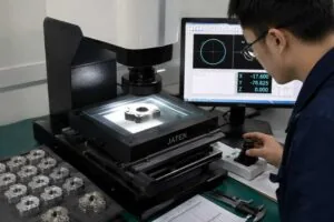
Two consequences follow for procurement. First, a supplier who cannot state the uncertainty of the measurement cannot prove conformity at this band, only assert it — which is why CNC machining quality control at ±0.005 mm is a metrology question before it is a machining one. Second, the drawing should say which decision rule applies. If both parties accept simple acceptance instead, the shared risk changes and both should know it.
Temperature: the error nobody puts on the drawing
Dimensional specifications apply at the 20 °C standard reference temperature of ISO 1:2016. Anything measured at another temperature is a different dimension, and at a ten-micrometre band the difference is not academic.
Worked example: one degree on a 100 mm feature
Length change is ΔL = L × α × ΔT. For 100 mm of steel with a coefficient of about 12.3 µm/m per K, one degree above reference gives
ΔL = 0.100 m × 12.3 µm/m/K × 1 K = 1.23 µm, about 12 per cent of the zone
The same feature in aluminium 6061, at about 23.6 µm/m per K, gives 2.36 µm — roughly a quarter of the zone from a single degree.
| Material | Expansion coefficient (µm/m per K) | Growth of a 100 mm feature per °C | Share of a 0.010 mm zone |
|---|---|---|---|
| Aluminium 6061-T6 | about 23.6 | 2.36 µm | about 24 per cent |
| Stainless 304 | about 17.3 | 1.73 µm | about 17 per cent |
| Alloy steel 4140 | about 12.3 | 1.23 µm | about 12 per cent |
| Ti-6Al-4V | about 8.6 | 0.86 µm | about 9 per cent |
Three practical points. Parts must reach thermal equilibrium before inspection, which for a large aluminium component is hours, not minutes. Coolant temperature matters as much as room temperature, because it sets the workpiece temperature during the cut. And where the assembly will run hot, the sensible engineering question is whether the fit needs to hold at 20 °C or at service temperature — those are different drawings.
Which features genuinely earn ±0.005 mm
A tolerance is earned when a functional requirement fails without it. The table separates the cases that do from the ones that are usually habit.
| Feature | Does it earn ±0.005 mm? | Reasoning |
|---|---|---|
| Rolling-element bearing seat | Often yes on small and medium diameters | Interference or clearance governs preload and bearing life; the bearing supplier states the fit |
| Dynamic sealing diameter | Frequently yes | Seal compression is set by diameter and surface texture together; specify both, per ISO 21920-2:2021 |
| Press or shrink fit | Depends on interference | What matters is the interference range, which may permit a wider band on a larger diameter |
| Location pin and its bore | Usually position, not size | Positional control under ASME Y14.5 typically does more than tightening size |
| Clearance hole for a fastener | Almost never | Clearance absorbs far more than ten micrometres |
| Cosmetic or non-mating face | No | Nothing mates; surface texture is the real requirement |
| Overall envelope dimensions | No | General tolerances are sufficient and far cheaper to verify |
Everything not in the first three rows should normally fall to the drawing’s general tolerance. MW+ works to ±0.01 mm against ISO 2768-m as a general standard, so a part with three genuinely critical features and a sensible general note is materially cheaper to verify than one where every dimension is tightened. Marking that distinction on the drawing is the highest-return five minutes available in the whole process. The companion article on tolerance standards for precision machined parts covers how the standards themselves differ between industries.
What changes on the shop floor at this band
Between a general tolerance and ±0.005 mm, a handful of things change in kind rather than in degree.
Roughing and finishing separate
Stock removal induces stress relief and heat. At this band the finishing pass must run on a part that has already released most of its residual stress, which usually means a separate operation, sometimes after an intermediate stress-relief step. A part cut in one continuous pass will move after the tool leaves.
Tool wear becomes a measured variable
A finishing tool wearing by a few micrometres across a batch consumes a visible share of the zone. Control means either an offset correction driven by in-process measurement, or a tool-change interval set so the wear across the interval stays within its share of the budget. Both are deliberate decisions, and the drawing’s band is what sets them.
Inspection moves upstream
Final inspection cannot recover a batch. The economic route is measurement early enough to correct the offset, which also means the fixture must present the part the same way every time. This is where the process discipline behind CNC precision parts differs from ordinary production work: the goal is to keep the process centred, not to find the parts that drifted.
What does the inspection report have to show?
At ±0.005 mm a report of pass or fail is not enough, because it hides whether the process is centred and whether the measurement could resolve the result at all. A usable report carries four things.
| Item | Why it matters at this band |
|---|---|
| Actual measured values, not just in-tolerance flags | Shows where in the zone the process is running and whether it is drifting |
| Instrument identity and its stated uncertainty or MPE | Without it, conformity under ISO 14253-1 cannot be demonstrated |
| Measurement temperature, or a statement of equilibrium | A result recorded away from 20 °C is a different dimension |
| Capability data across the batch, not a single article | One good first article says nothing about the hundredth part |
Every MW+ order ships with a certificate of conformance, a CMM inspection report and material certificates, with first article inspection to AS9102 or PPAP Level 3 quoted per programme. Where sampling rather than 100 per cent inspection is agreed, the plan should be named: ISO 2859-1:2026, which supersedes the 1999 edition, is the usual reference for attribute sampling by acceptance quality limit.
When ±0.005 mm is the wrong call
This band is expensive to hold and expensive to prove, and there are four common cases where it buys nothing.
The assembly is over-constrained anyway
If three features locate one part against another, tightening all three does not improve fit; it makes assembly harder and can make it impossible. The correct fix is a datum scheme that lets one feature locate and the others follow, which usually widens two tolerances rather than tightening three.
The measurement cannot resolve it
Where the available instrument has an expanded uncertainty near 0.003 mm, the conformance zone collapses to 0.004 mm and most conforming parts cannot be proven conforming. Specifying a band the measurement chain cannot support generates disputes, not quality. Either invest in the measurement or widen the tolerance.
The part moves more than the tolerance in service
A thin-walled aluminium housing that grows two micrometres per degree will move further across its operating range than the tolerance you fought for at 20 °C. If service temperature varies, the design should absorb the movement rather than the drawing trying to remove it.
Form or position is the real requirement
Roundness, cylindricity and true position are frequently what the function actually depends on, and tightening a size tolerance is an indirect and expensive way of chasing them. Controlling the right characteristic under ISO 1101:2017 is usually both cheaper and more effective. The sibling comparison of ±0.01 mm against ±0.005 mm is worth reading before committing, and budgeting for ±0.005 mm covers the commercial side.
Frequently asked questions
Does ±0.005 mm mean every part will measure near nominal?
No. Any value inside the zone is conforming, and a capable process that runs consistently at one edge is behaving correctly. If the design needs the dimension near the middle, the drawing must say so — usually by narrowing the band asymmetrically rather than by expecting the supplier to infer the intent.
Can ±0.005 mm be held in every material?
The band is achievable across a wide range, but the effort differs sharply. Materials that are dimensionally stable and cut cleanly — hardened steels, titanium alloys, many stainless grades — are the easier cases. Soft and gummy alloys, thin sections and materials with high expansion coefficients are harder, not because the machine cannot position but because the workpiece moves. Aluminium is the common surprise: easy to cut, and the least thermally stable of the common metals.
Do I need 100 per cent inspection at this band?
Not necessarily. What is needed is evidence that the process stays centred, which capability data across the batch provides more cheaply than measuring every part. Where the characteristic is safety-critical or the consequence of an escape is severe, 100 per cent inspection is justified — and then the instrument’s uncertainty determines how much of the zone remains usable.
Why did my supplier reject a part that measured inside the tolerance?
Almost always because of the decision rule. Under ISO 14253-1, a measured value in the guard band between the specification limit and the reduced conformance limit is neither proven conforming nor proven non-conforming, and a supplier working to that rule will not ship it. Agreeing the decision rule in advance prevents the argument entirely.
Is ±0.005 mm the same as five microns of accuracy?
No, and the confusion is expensive. ±0.005 mm is a ten-micrometre zone, so a machine whose positioning repeatability is quoted as five micrometres has already spent half of it. Machine specifications are stated under ISO 230-2:2014 and describe the machine, not the part; the part’s result is the sum of the machine, the setup, the tool, the material and the measurement.
Should I tighten the tolerance or add a geometric control?
Ask what fails if the feature is at the edge of a wider band but perfectly round and correctly located. If nothing fails, the problem was form or position, and a geometric control is the cheaper and more direct answer. Tightening size to fix a form problem raises cost across the whole feature while leaving the actual failure mode untouched.
How much smaller can the band go?
Below ±0.005 mm the constraints change in kind: temperature control, measurement uncertainty and machine thermal behaviour start to dominate, and process routes narrow towards grinding, honing and micro machining services. MW+ holds down to ±0.001 mm where a feature genuinely requires it, and the article on what it takes to hold ±0.001 mm sets out what that demands. Before going there, confirm that the function needs it; most features that arrive specified at ±0.001 mm do not.
If you have a drawing at this band and want the tolerances reviewed against what the function requires, you can request a CNC machining quote with the model attached. MW+ has machined to these bands since 2015 from a 15,000 m² facility in Shenzhen, with 60+ CNC machining centres, 120+ engineering and quality professionals, and ISO 9001:2015, AS9100D, ISO 13485, IATF 16949 and NADCAP approvals; quotations are returned within 24 hours.