Halving a tolerance band does not simply double the difficulty. It moves three things at once: what the machine must hold, what the measuring system can prove, and what workshop temperature does to the part while you measure it. This page compares ±0.01 mm and ±0.005 mm on all three, with the arithmetic shown, and is explicit about when the tighter band is the wrong thing to ask for.
Key takeaways
- ±0.01 mm is a 20 µm band; ±0.005 mm is a 10 µm band. To hold Cpk ≥1.67 on a centred process, the standard deviation must be no more than 2.0 µm and 1.0 µm respectively — the calculation is below.
- Temperature can consume the whole band. A 200 mm aluminium feature 5 °C above the 20 °C reference of ISO 1:2022 grows about 23.6 µm, more than twice the ±0.005 mm band.
- Measurement uncertainty eats into the band before machining does. Under ISO 14253-1:2017, an expanded uncertainty of 2 µm shrinks a 10 µm conformance zone to 6 µm.
- Tighten characteristics, not parts. A drawing with one ±0.005 mm bore and everything else to ISO 2768-m costs far less than a blanket tight callout and gives the same function.
- MW+ works to ±0.01 mm generally to ISO 2768-m, ±0.005 mm as a precision band and ±0.001 mm on selected features, with Cpk ≥1.67 on controlled characteristics and a CMM report with every order.
- What the two callouts actually mean
- How do the two bands compare in practice?
- What does Cpk have to do with your tolerance?
- Why does temperature decide whether ±0.005 mm is even real?
- Can the tolerance be measured at all?
- Which standards govern general and geometrical tolerances?
- What makes the tighter band cost more?
- Which features actually need ±0.005 mm?
- When ±0.005 mm is the wrong specification
- Writing a tolerance callout that can be quoted
- Frequently asked questions
What the two callouts actually mean
A bilateral callout of ±0.01 mm permits the feature to lie anywhere in a band 0.02 mm wide — 20 micrometres. ±0.005 mm halves that to a 10 µm band. For scale, a human hair is roughly 70 µm across, so the tighter band is about one seventh of a hair’s width, total, for every part in the batch.
Both bands are routine for a competent shop on the right feature and neither is routine on the wrong one. What decides it is not the number but the feature: its size, its material, how it is held, and whether the dimension is measured from a datum established in the same setup. That last point matters more than band width, which is why a ±0.01 mm cross-face relationship can be harder than a ±0.005 mm diameter.
How do the two bands compare in practice?
The table below sets out what changes on the shop floor. It carries no cost percentages or scrap rates, because any such figure is specific to a part, a material and a shop; quoting one as an industry constant is how tolerance decisions go wrong.
| Factor | ±0.01 mm | ±0.005 mm | Why it changes |
|---|---|---|---|
| Total band | 20 µm | 10 µm | Every other contributor now has half the room |
| Required process σ for Cpk ≥1.67 | 2.0 µm | 1.0 µm | Calculated below; the process itself must be twice as stable |
| Finishing strategy | Single finishing pass usually sufficient | Separate spring pass, lighter depth of cut | Tool pressure deflects the part and the tool |
| Tool wear management | Monitored across the shift | Offset compensation within the batch | Edge wear of a few microns now moves the dimension out |
| Temperature | Usually tolerable on a normal floor | Must be controlled or corrected | See the thermal calculation below |
| Measurement | Hand gauging often adequate | CMM with stated uncertainty and a decision rule | Uncertainty consumes a fixed share of a narrower band |
| Datum discipline | Tolerable across setups on many parts | Usually forces a single setup | Re-location error is a direct contributor |
| Material behaviour | Most alloys behave predictably | Residual stress and spring-back become visible | Relaxation after stock removal is of the same order as the band |
What does Cpk have to do with your tolerance?
A tolerance is a statement about every part, not one good part, and process capability is how that becomes something a shop can plan against. For a centred process, Cpk = (USL − μ) ÷ 3σ, with USL the upper limit, μ the process mean and σ the standard deviation.
Work it backwards to find the stability a band demands at Cpk ≥1.67:
- At ±0.005 mm: σ = 0.005 ÷ (3 × 1.67) = 0.005 ÷ 5.01 = 0.000998 mm, about 1.0 µm
- At ±0.01 mm: σ = 0.010 ÷ 5.01 = 0.001996 mm, about 2.0 µm
Now add a realistic complication. Suppose the process at ±0.005 mm holds σ = 1.0 µm but drifts 1 µm off centre as the tool wears. Capability becomes Cpk = (5 − 1) ÷ (3 × 1) = 1.33. A single micrometre of mean shift — far less than the band, and invisible on any individual part — has taken the process from comfortably capable to marginal. That is why tight-tolerance work is offset-compensated within the batch rather than set once at the first-off, and why the inspection plan matters as much as the machine. Our approach to that is set out under CNC machining quality control.
Why does temperature decide whether ±0.005 mm is even real?
Dimensional specifications are defined at a standard reference temperature of 20 °C under ISO 1:2022. Away from 20 °C, the part is a different size, and the change is calculated as ΔL = α × L × ΔT, where α is the coefficient of linear thermal expansion.
Take a 200 mm aluminium feature measured at 25 °C, five degrees above reference, using a typical published α of 23.6 µm/(m·K) for 6061:
- ΔL = 23.6 × 10⁻⁶ /K × 200 mm × 5 K = 0.0236 mm, or 23.6 µm
- That is 2.4 times the entire ±0.005 mm band, and still larger than the ±0.01 mm band
- On a 50 mm feature the same conditions give 5.9 µm, which is over half the ±0.005 mm band on its own
So a ±0.005 mm callout on a long aluminium dimension is not a machining question first. It is a question of whether part and instrument are at a known temperature and whether a correction is applied. A supplier who accepts such a callout without asking has not thought about it.
| Material | Typical α, µm/(m·K) | Growth on 100 mm at ΔT = 5 K | Share of a 10 µm band |
|---|---|---|---|
| Invar 36 | ≈1.2 | 0.6 µm | 6% |
| Ti-6Al-4V | ≈8.6 | 4.3 µm | 43% |
| Carbon steel, 1045 | ≈11.5 | 5.8 µm | 58% |
| Stainless 316L | ≈16.0 | 8.0 µm | 80% |
| Stainless 303 | ≈17.3 | 8.7 µm | 87% |
| Brass C360 | ≈20.5 | 10.3 µm | 103% |
| Aluminium 6061 | ≈23.6 | 11.8 µm | 118% |
The practical reading: on brass and aluminium, a five-degree excursion can use the whole ±0.005 mm band on a 100 mm feature before the machine has done anything wrong. On titanium and Invar there is room to work.
Can the tolerance be measured at all?
Every measurement has an uncertainty, and ISO 14253-1:2017 sets out how that uncertainty is handled when deciding whether a part conforms. Under the default rule, the uncertainty is taken off the specification zone at each limit, so the zone in which conformity can actually be proved is narrower than the zone on the drawing.
Put numbers on it. Suppose the measuring system has an expanded uncertainty U = 2 µm on the feature in question:
- At ±0.005 mm the drawing zone is 10 µm; the conformance zone becomes 10 − (2 × 2) = 6 µm, an effective ±0.003 mm
- At ±0.01 mm the drawing zone is 20 µm; the conformance zone becomes 20 − 4 = 16 µm, an effective ±0.008 mm
- The same 2 µm uncertainty consumes 40% of the tight band and 20% of the looser one
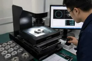
That is the hidden cost of halving a band: the measuring system must improve too, or you reject good parts and pass marginal ones. Coordinate measuring machines are accepted and reverified against ISO 10360-2:2009 — the document to name when you want evidence of what a supplier’s CMM resolves. Ask for the stated uncertainty on your feature, not a machine model number.
Which standards govern general and geometrical tolerances?
Most drawings carry a general-tolerance note and a handful of individual callouts. Getting the note right matters more than tightening individual dimensions, because it governs everything you did not think about.
| Standard | What it governs | Status |
|---|---|---|
| ISO 2768-1:1989 | General linear and angular tolerances where none is indicated; classes f, m, c, v | Current |
| ISO 2768-2:1989 | General geometrical tolerances | Withdrawn — replaced by ISO 22081:2021 |
| ISO 22081:2021 | General geometrical and general size specifications | Current |
| ISO 286-1:2010 | ISO code system for tolerances on linear sizes; IT grades and fits | Current |
| ISO 1101:2017 | Form, orientation, location and run-out tolerances | Current |
| ASME Y14.5-2018 | GD&T in the North American convention | Current, reaffirmed 2024 |
| ISO 21920-2:2021 | Surface texture parameters, superseding ISO 4287:1997 | Current |
| ISO 14253-1:2017 | Decision rules for verifying conformity, including uncertainty | Current |
Two traps recur. ISO 2768-2:1989 is still printed on title blocks across the industry even though it has been withdrawn and replaced by ISO 22081:2021, so state which convention governs rather than assuming. And ISO 4287:1997 is superseded by ISO 21920-2:2021 for surface texture parameters, with the indication rules moving to ISO 21920-1:2021 in place of ISO 1302; both conventions remain in circulation, so the drawing must say which one it is written to. A fuller walk through the general-tolerance classes is in our article on precision machined parts and tolerance standards.
What makes the tighter band cost more?
Not the cut. A finishing pass at ±0.005 mm removes the same metal as one at ±0.01 mm. The cost sits in everything arranged around the cut so that the result is repeatable and provable.
| Driver | What changes at ±0.005 mm | Charged how |
|---|---|---|
| Process proving | More first-off pieces before the offsets settle | Once per batch |
| Cutting strategy | Lighter finishing cuts, sometimes a spring pass | Every part |
| Tool management | Offsets compensated within the batch, not per shift | Every part, plus tool consumption |
| Setup consolidation | Features forced onto a single setup to remove re-location error | Fixture design and machine class |
| Environment | Part and gauge brought to a known temperature before measuring | Cycle time and floor space |
| Inspection | Higher sampling, stated uncertainty, documented decision rule | Per part or per lot, per the plan |
| Material selection | Stress-relieved or more stable stock may be required | Material and lead time |
Because these are different kinds of charge — some fixed per batch, some per part — the premium for a tight band is not a single percentage, and anyone quoting one is guessing. Ask which rows above your part triggers: if only the first two, the increment is modest; if all seven, it is not. How that stacks up over a programme is covered in our piece on the cost impact of ±0.005 mm accuracy in production.
Which features actually need ±0.005 mm?
The honest test is functional: what fails if the feature sits at the edge of the looser band? If nothing does, the looser band is correct, whatever the rest of the drawing says.
| Feature | Usually adequate | Needs the tighter band when |
|---|---|---|
| Bearing seat or press fit | Specify a fit per ISO 286-1, not a bilateral band | The fit class itself lands inside 10 µm |
| Sealing land for an O-ring | ±0.01 mm on the groove width | Compression set is critical and the seal is small |
| Clearance hole | ISO 2768-m is normally ample | Almost never |
| Dowel or location pin bore | Fit class per ISO 286-1 | The location itself is the datum for a tight assembly |
| Optical or fluidic orifice | Depends entirely on flow or beam tolerance | Performance varies measurably within 10 µm |
| Mating faces on an assembly stack | ±0.01 mm each, with the stack analysed | The stack analysis shows no other way to close it |
| Cosmetic or clearance surfaces | General tolerance | Never |
Note the first and fourth rows. For mating features an ISO 286-1 fit designation such as H7/g6 states the intent directly and lets the limits scale with size, which is usually cheaper and more correct than a fixed ±0.005 mm at every diameter. Parts that genuinely sit here are the ones we quote as CNC precision parts; features below this band again are covered in our article on what ±0.001 mm accuracy requires.
When ±0.005 mm is the wrong specification
Tighter is not safer. A band the process cannot prove is a band that generates disputes, and a drawing that over-specifies is a drawing that gets quoted defensively.
When the measuring system cannot resolve it
If the uncertainty on your feature is 3 µm, an effective conformance zone of 4 µm remains inside a ±0.005 mm callout. At that point the specification is being decided by the gauge, not the process, and inspection disagreements between you and your supplier are guaranteed. Fix the metrology or loosen the band.
When the material will not hold still
Thin-walled aluminium, drawn bar with residual stress and unstabilised castings can move by more than 10 µm after the clamping force is released or the stock is removed. A tighter band on such a part does not produce a more accurate part; it produces a part that was in tolerance on the machine and out of tolerance on the bench.
When the tolerance belongs on the assembly
Sometimes the real requirement is a relationship — a running clearance, a preload, a seal compression — and the drawing has pushed it onto one dimension because that was easier than analysing the stack. Doing the stack analysis often shows that two features at ±0.01 mm close the requirement perfectly well, at a fraction of the cost of one at ±0.005 mm.
When it is applied to the whole drawing
A general note of ±0.005 mm on every dimension is the single most expensive line on a drawing and is almost never what the designer meant. Set the general note to ISO 2768-m and call out the two or three features that genuinely need more. That one change usually saves more than any process improvement a supplier could offer.
Writing a tolerance callout that can be quoted
A tolerance is quotable when a supplier can see what is being measured, from where, at what temperature and against which decision rule.
| What to state | Why it changes the quote | If omitted |
|---|---|---|
| General tolerance class and its standard | Governs every undimensioned feature | Supplier assumes the tightest plausible class |
| Datums for every geometrical callout | Decides whether features must share a setup | Route split across setups; stack-up appears late |
| Which two or three features are critical | Lets the rest run to the general tolerance | Everything inspected as if critical |
| Fit designation where a fit is the intent | Lets the limits scale correctly with size | A symmetrical band that is wrong at one end |
| Measurement temperature and any correction | Makes the callout physically meaningful | Disagreement at receiving inspection |
| Decision rule and required documentation | Sets the sampling plan and the reporting effort | Reporting scope discovered after the parts are cut |
| Material grade, temper and stock condition | Determines stability and expansion behaviour | Parts that pass on the machine and fail on the bench |
Every MW+ order ships with a certificate of conformance, a CMM inspection report and material certificates; AS9102 first article inspection and PPAP Level 3 are quoted per programme. Send a STEP model, a drawing with datums and a note of which dimensions are genuinely critical, and a quote comes back within 24 hours with a straight answer on whether we can hold and prove the band. If you are unsure which features need tightening, request a CNC machining quote and say so — that question is cheaper before the drawing is released than after.
Frequently asked questions
Is ±0.005 mm twice as expensive as ±0.01 mm?
There is no fixed multiplier, and anyone quoting one is generalising from a different part. The increment depends on which cost drivers your feature triggers. Tightening one bore on an otherwise ordinary part may add very little; tightening a cross-face relationship can force a different machine, fixture and inspection plan. Ask your supplier which drivers apply.
Why did my supplier query a tolerance they say they can hold?
Usually because the callout is achievable but not provable, or because it is achievable on the machine and not after the part relaxes. Both are worth raising before cutting. A supplier who queries a band is doing the job; one who accepts every band without comment is deferring the conversation to receiving inspection.
Should I put ±0.005 mm in the title block to be safe?
No. A blanket tight general tolerance applies to every dimension including the ones nobody cares about, and it forces the supplier to plan, machine and inspect all of them to that band. Set the general note to a published class such as ISO 2768-m and tighten individual features. The saving from that one change is usually larger than anything else available on the drawing.
Does a ±0.005 mm part need a 5-axis machine?
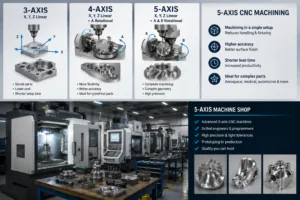
Only if the tolerance crosses a setup boundary. A single-face dimension at ±0.005 mm can be held on a well-maintained 3-axis machine. A positional relationship between features on different faces at that band usually cannot, because the re-location error alone is of the same order as the tolerance. The distinction is worked through in our comparison of 3-axis and 5-axis cost and accuracy.
What tolerance applies if my drawing says nothing?
Whatever the general note says, and if there is no general note, whatever the supplier decides to assume — which is not a position you want to be in. ISO 2768-1:1989 provides classes f, m, c and v for linear and angular dimensions; general geometrical specifications now come from ISO 22081:2021. State the class and the standard explicitly in the title block.
How do I check that a supplier can really hold ±0.005 mm?
Ask for three things: the stated measurement uncertainty on a feature of your size, the decision rule they apply under ISO 14253-1, and capability data on a comparable characteristic. A shop that holds the band routinely will have all three to hand. A shop that quotes a machine model instead is answering a different question.
Can surface finish requirements conflict with a tight tolerance?
Yes, and it is a common trap. Roughness is a deviation about the mean surface, so on a 10 µm band a coarse finish consumes a meaningful share of it before any other error is counted. If you need ±0.005 mm on a feature, specify the surface texture on the same feature to ISO 21920-1:2021 as well, so the two requirements are designed together rather than discovered in conflict.