







Hydraulic spool valve clearance should be specified for the actual spool–bore pair, with a clear distinction between diametral clearance, radial clearance and the conditions of inspection. Clearance is only one part of the valve design. Moog’s discussion of null-cut configurations distinguishes radial fit from the relationship between the land edges and ports; those metering arrangements also influence leakage and response. [1]
Illustrative application guide: This is a drawing-and-inspection study, not an MW+ customer project or a qualified valve design. Every dimension, displayed reading and selection target below is assumed. The calculations establish neither an acceptable running fit nor a leakage rate. No hydraulic test, pressure rating, safety function or complete valve-manufacturing capability is claimed.
Contents
Hydraulic spool valve clearance: define the spool–bore pair
Identify the controlled land and the bore or sleeve against which it runs. Mark the axial extent of the land, corresponding bore region, relevant ports and required travel on a sectioned drawing. State whether the bore is in a separate sleeve or another component. Keep each land identifiable where one spool has several controlled regions.
For the ideal circular, concentric geometry used in this guide, define diametral clearance as Cd = Dbore − Dspool. Define the corresponding radial clearance as Cr = Cd/2. These are geometric definitions. They describe a uniform radial gap only for the stipulated concentric circular section; they do not describe the smallest local gap of an eccentric or imperfect actual assembly.
Write the word “diametral” or “radial” beside a clearance value. Moog’s historical contamination paper explicitly marks certain spool-to-sleeve values as radial in its comparison table. [2] That makes it a useful terminology warning, not a source of approved dimensions for this example. None of its typical clearance ranges is adopted here.
State the condition for each valve spool tolerance
Our recommended drawing review records material, relevant treatment stage, measurement temperature and support condition. Identify whether the reported dimension belongs to a loose component, an installed sleeve or the completed assembly. Ask the design owner which condition governs acceptance and what must be checked again after assembly.
A useful enquiry distinguishes the released requirement from a supplier’s process target. For example, a proposed machining allowance can be discussed without changing the final spool diameter. Require approval for any alteration to a controlled feature or its acceptance condition rather than letting a process assumption become an undocumented design change.
Calculate a spool to bore clearance budget with explicit units
Assumed inputs: Let the bore diameter be 10.000–10.004 mm and the spool land diameter be 9.990–9.994 mm. These are invented component limits. They are not standard fit classes, recommended hydraulic clearances or MW+ production tolerances. Assume circular coaxial sections solely to examine the subtraction.
The smallest diametral clearance combines the smallest bore with the largest spool: 10.000 − 9.994 = 0.006 mm. The largest combines the largest bore with the smallest spool: 10.004 − 9.990 = 0.014 mm. Convert millimetres to micrometres by multiplying by 1,000, then divide by two for the ideal radial value.
| Combination | Assumed bore (mm) | Assumed spool (mm) | Calculated diametral clearance (µm) | Ideal concentric radial clearance (µm) |
|---|---|---|---|---|
| Smallest clearance | 10.000 | 9.994 | 6 | 3 |
| Midpoint illustration | 10.002 | 9.992 | 10 | 5 |
| Largest clearance | 10.004 | 9.990 | 14 | 7 |
The midpoint subtraction is 10.002 − 9.992 = 0.010 mm, or 10 µm diametral. The full component-limit calculation permits 6–14 µm diametral, not merely the midpoint value. Reporting only “10 µm clearance” would conceal the variation allowed by these assumptions.
This budget answers a dimensional question, not a functional one. There is no fluid, differential pressure, temperature range, land length, metering configuration or permissible leakage specified. Do not label any row acceptable for operation. Ask the valve designer to define the functional requirements and the analysis or tests needed to judge the proposed dimensional interval.
Compare interchangeability with an assumed matched-pair target
The second table asks a different question: what happens if assembly selection depends on the individual pair? Assume two bore readings and two spool readings, all within the component limits above. Invent a separate assembly-selection target of 9–11 µm diametral. That target is a teaching input, not an approved valve requirement.
| Pair identifiers | Assumed bore reading (mm) | Assumed spool reading (mm) | Calculated diametral clearance (µm) | Comparison with assumed selection target |
|---|---|---|---|---|
| B1 + S1 | 10.001 | 9.991 | 10 | Inside the assumed numerical target |
| B2 + S2 | 10.003 | 9.993 | 10 | Inside the assumed numerical target |
| B1 + S2 | 10.001 | 9.993 | 8 | Below the assumed target; engineering review needed |
| B2 + S1 | 10.003 | 9.991 | 12 | Above the assumed target; engineering review needed |
Every individual reading lies within the invented component band, yet swapping the pairs changes the numerical outcome against the narrower invented selection target. This illustrates why component conformity and a pairing rule must be documented separately. It does not establish a need for selective assembly in every hydraulic valve.
If an actual design requires matched pairs, our recommendation is to record both component identities, the approved pairing rule and the inspection record. Define how the pair is marked, stored and supplied. Ask whether replacement components must be reselected or can be independently interchanged. Do not infer interchangeability from equal nominal diameters.
Keep spool valve leakage, metering and contamination separate
Moog distinguishes zero-overlap, underlap and overlap configurations by the relationship between spool land edges and ports near the centered position. [1] In the drawing review, therefore, identify both the radial-fit features and the axial metering features. A bore-minus-spool calculation does not specify the whole valve.
Moog also describes excessive leakage associated with worn spool/bushing lands in a particular service case. [3] That is manufacturer evidence of a mechanism in its reported application, not a leakage prediction, lifetime estimate or repair recommendation for another component. This guide transfers none of the case’s numerical results.
Define the leakage question before selecting a test
Ask the system owner to identify the flow path being evaluated, valve position, port pressures, fluid and temperature condition. Specify whether the acceptance requirement concerns internal flow between ports or external escape from the assembly. Record the measurement arrangement and required stabilization condition in the proposed test plan.
This guide deliberately supplies no clearance-to-leakage formula or flow-rate result. A real prediction needs an applicable model and inputs for the actual geometry and operating state. Do not substitute a calculated size difference for measured leakage, or use one product’s catalog leakage limit as a universal acceptance criterion.
Review cleanliness alongside the mechanical fit
A useful fit review considers more than avoiding contact. Moog’s contamination paper describes particles lodging between the spool and its mating part, as well as fine-particle accumulation during stationary operation. It also associates wear at control lands with increased null leakage. These mechanisms explain why a clearance value, cleanliness plan and wear assessment should be reviewed together. They do not establish a universally optimal gap. [2]
Moog’s contamination paper describes particle jamming and silting as distinct mechanisms affecting spool operation. [2] Use that context to ask who owns fluid cleanliness, component cleaning and contamination-control requirements. Do not derive a filter rating from Table 1 or assume that making a gap smaller resolves every failure mode.
For procurement, keep the cleanliness requirement separate from the supplier’s general statement that a part is deburred or washed. Request the approved acceptance description, method and evidence needed for the intended assembly. The surrounding manifold has its own passage and cavity questions; those belong in the hydraulic manifold machining guide, subject to confirming the applicable component interface.
Prepare machining and surface requirements for the spool land
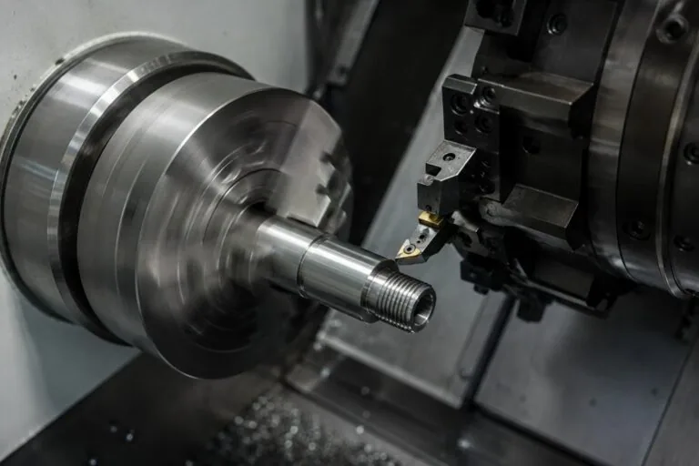
Mark the controlled land diameters, axial lengths, groove boundaries and relevant datum relationships on the drawing. Ask the supplier to explain the proposed manufacturing sequence and how final inspection will verify each released characteristic. Discuss whether later processing requires a dimensional allowance rather than assigning a generic allowance without a process proposal.
Keep size, form and surface-texture requirements explicit. Ask which characteristics must be inspected independently and where the drawing defines them. For general hole-finishing choices, refer to boring versus reaming; neither process name establishes an acceptable spool fit. This application study does not prescribe grinding, honing, lapping or a particular combination as universally necessary.
Review critical edges with the valve designer. Identify which edge geometry is functional and which edges can receive an approved treatment. Ask how the supplier will prevent an ambiguous deburring note from becoming an unintended change to a controlled land or port interface. Obtain approval for any proposed alteration rather than relying on an attractive surface finish alone.
Plan inspection and assembly verification as separate records
NPL’s CMM measurement-strategy guide addresses sampling, loading and alignment, temperature, surface finish and geometry in relation to measurement results. [4] Use those considerations when reviewing a proposed inspection plan; they do not establish that a CMM is the right instrument for every feature or clearance interval.
Request the measurement method, locations, component condition and uncertainty information for the actual spool and bore. Ask how the method covers the controlled length and relevant circumferential positions. Keep the individual observations linked to the feature and axial location rather than reporting a single unlabeled diameter.
Where the drawing includes form or alignment requirements, define how those are evaluated. Do not silently treat a local size reading as a complete evaluation of cylindricity, straightness or the assembled local gap. The ideal concentric radial values in Table 1 should remain labelled as geometric illustrations.
Check whether the reported readings resolve the pairing decision
Original bounded-error illustration: Keep the assumed B1 reading of 10.001 mm and S1 reading of 9.991 mm from Table 2. Now additionally assume that each true local diameter lies within ±0.001 mm of its displayed reading. These are invented error bounds, not the capabilities of an instrument or an actual calibration statement.
The assumed true bore interval is then 10.000–10.002 mm and the assumed true spool interval is 9.990–9.992 mm. Subtracting opposite extremes gives a possible diametral clearance of 10.000 − 9.992 = 0.008 mm to 10.002 − 9.990 = 0.012 mm, or 8–12 µm. Although the central subtraction is 10 µm, this bounded interval extends outside the illustrative 9–11 µm selection target.
The practical decision is to resolve the measurement and acceptance method, rather than declare the pair accepted from its central reading. This is conservative interval arithmetic for stipulated bounds. It is not a calculation of combined expanded uncertainty, a confidence interval or a prescribed conformity rule. In a real inspection plan, agree how the actual uncertainty and decision rule affect acceptance with the responsible engineering and metrology teams.
Plan functional verification separately. Identify the assembly revision, selected pair where applicable, operating conditions and approved acceptance criteria. A dimensional inspection report and a hydraulic test report should retain their distinct purposes. Neither table in this guide supplies real test data, pressure qualification or evidence of a safety-related function.
Release checklist and manufacturing next steps
- Identity: Name the spool, mating bore, controlled lands and revisions.
- Units: Label radial versus diametral clearance explicitly.
- Limits: Calculate component-limit combinations rather than only nominal subtraction.
- Assembly: State interchangeability or the approved matched-pair rule.
- Features: Define axial metering geometry, form, texture and edges separately.
- Conditions: Identify measurement stage, support, temperature and uncertainty review.
- Validation: Assign responsibility for leakage, motion and cleanliness acceptance.
Discuss the controlled component within MW+’s machined mechanical parts range. For cylindrical-feature planning, review the CNC turning service with the actual drawing. Use the manufacturing and inspection review to resolve the proposed process and records. Send MetalWorksPlus the released component drawings and assembly requirements together; confirm the supplied component scope and hydraulic-validation responsibility separately.
Frequently asked questions
How do you specify hydraulic spool valve clearance?
Identify the controlled spool–bore pair, state radial or diametral convention, specify the component limits and measurement condition, and document the functional acceptance requirements separately. Start with the actual valve design and operating conditions; this guide provides no universal clearance. The tabulated dimensions are hypothetical teaching inputs.
Is radial clearance the same as diametral clearance?
No. In this guide’s ideal circular concentric model, diametral clearance is bore diameter minus spool diameter, and radial clearance is half that difference. State which definition the drawing uses.
Does a smaller clearance always produce a better valve?
No such conclusion follows from the calculations. Review leakage, motion, contamination and the complete geometry. Moog’s contamination discussion identifies jamming and silting mechanisms rather than a universal fit recommendation. [2]
Can conforming components require controlled pairing?
The hypothetical second table demonstrates that possibility when a separate, narrower selection target is assumed. An actual matched-pair requirement must be defined and approved, with traceability and replacement rules.
Does a diameter report prove acceptable spool valve leakage?
No. Keep dimensional results and functional verification separate. The actual leakage test must identify its flow path, valve position, fluid conditions and acceptance criteria; no leakage rate is calculated here.
Technical references and boundaries
- Moog: Customized Null Cutting and Optimized Performance. Land/port overlap distinctions and valve-level context; supplier design percentages and performance claims not transferred.
- R. W. Park, Moog: Contamination Control : A Hydraulic OEM Perspective, 1997. Historical technical paper on particle jamming, silting and valve design; typical numerical clearances, historical cleanliness targets and service intervals not adopted.
- Moog: Putting Servo Valves Back to Work, 2018. Reported worn-land leakage mechanism; project results and supplier service claims not attributed to MW+.
- NPL: CMM Measurement Strategies, GPG41. Public guide description covering measurement planning; no instrument capability or universal sampling count inferred.
Sources rechecked 5 November 2026. The two tables use original assumed inputs and independently checked arithmetic. Review questions are engineering recommendations; no standard fit, production capability or completed customer project is represented.