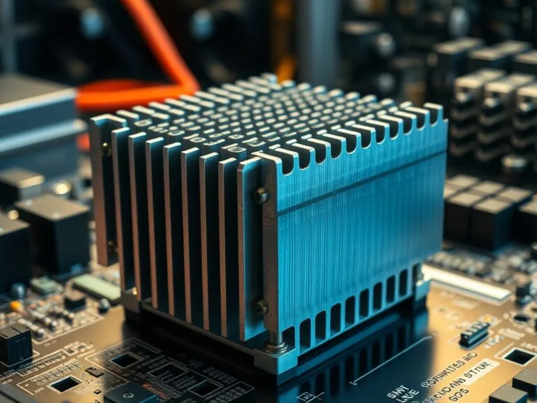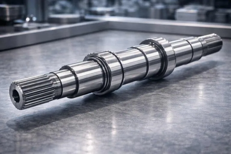








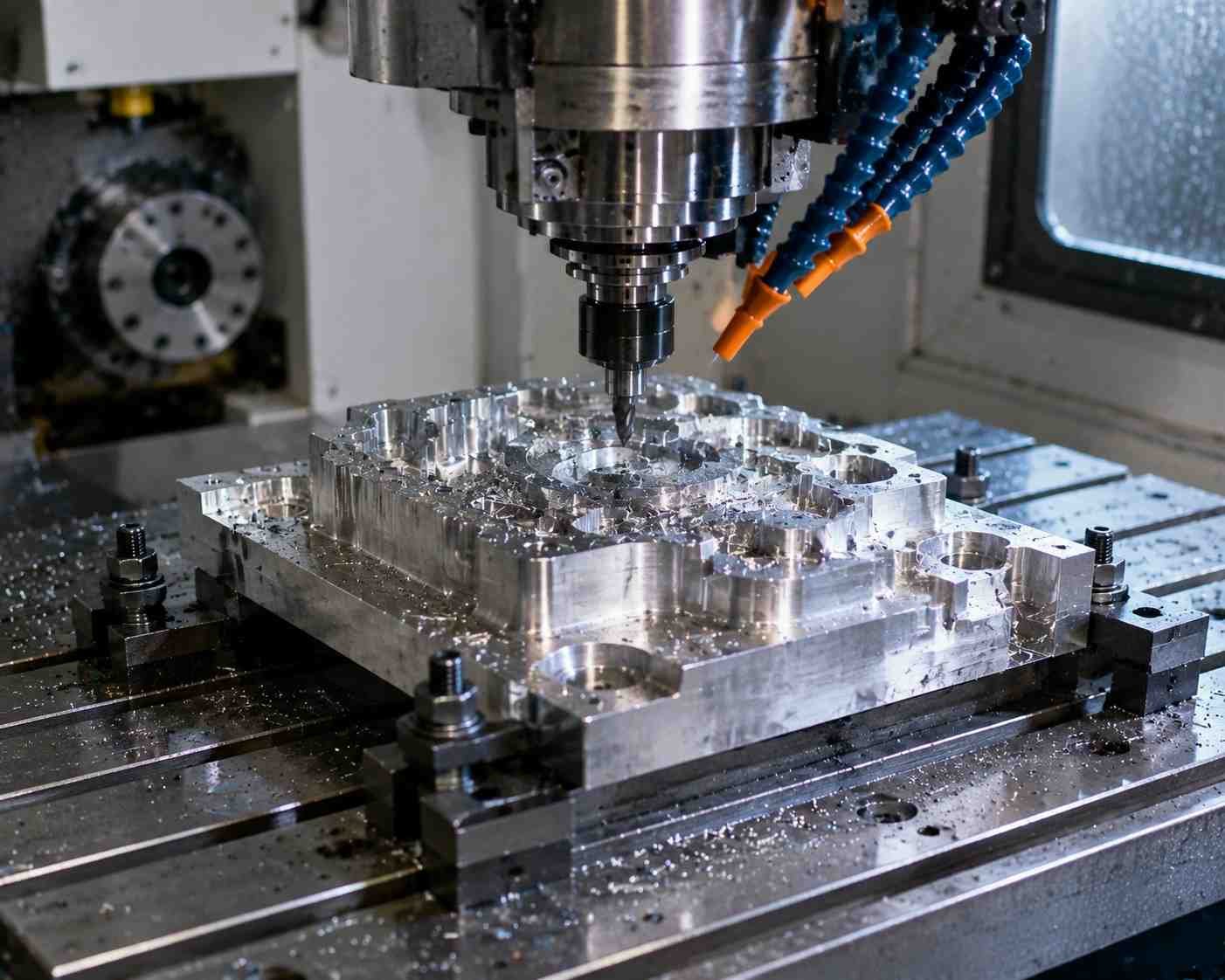
Liquid cold plate design should define the heat load, coolant conditions and allowable pressure loss before fixing channel geometry, cover construction and sealing features. A machined channel is one part of an assembly that must transfer heat, contain fluid and connect to a cooling loop. Review these functions separately, then verify them together under approved operating conditions. The OCP development guide addresses those distinct responsibilities for single-phase information-technology cold plates. [1]
Application-guide disclosure: this is an illustrative engineering guide, not an MW+ customer case study. Every numerical example below uses explicitly assumed inputs. No prototype, CFD result, leak test, pressure qualification, production outcome or validated cooling rating is claimed. The component illustration does not show the calculated example.
The intended reader is preparing a drawing and enquiry package for a machined base and mating cover. The proposed workflow asks what must be specified, what can be calculated from assumptions and what still needs specialist analysis or testing. It does not select a ready-to-use cooling assembly.
Contents
Define the liquid cold plate design requirements
Start with a requirement sheet that the thermal, mechanical and fluid-system owners can approve. Our recommendation is to identify each heat source, its footprint, the power profile and the temperature reference being controlled. Keep a device-case limit distinct from a coolant-outlet target; the two answer different questions.
Record coolant formulation and concentration, inlet-temperature range, proposed flow range and the pressure-loss allocation across the plate. Request the applicable pump and loop information. Eaton describes a loop comprising cold plate, pump, heat exchanger and connecting lines, with the coolant carrying heat onward to the exchanger. [3] A plate enquiry should therefore state its boundary conditions within that loop.
Next, mark mounting interfaces, external envelope, fitting access and hose routing on an assembly drawing. Specify who approves the finished assembly rather than assuming the component machinist owns thermal design, cover joining and fluid qualification. Ask each supplier to identify the scope it is quoting.
Choose the construction before detailing the channels
Boyd’s technical datasheet distinguishes tube-in-plate, vacuum-brazed and microchannel constructions. [2] A groove supporting a separate tube and a channel directly containing coolant have different component boundaries. Do not combine a tube manufacturer’s pressure rating with a machined-cover drawing and treat the result as an assembly rating.
For this guide, assume a proposed open-channel base and a separate mechanically retained cover. The seal remains subject to engineering selection. Our review checklist would identify the base, cover, retention hardware, ports and seal as individually controlled items, with a separate assembly specification. Alternative joining routes need their own approved drawings and process review; their mention here does not establish an MW+ offering.
Use a checked heat balance without claiming a cooling rating
For steady single-phase sensible heating, the energy balance is Q = ṁcp(Tout − Tin). Here Q is heat carried by the fluid in watts, ṁ is mass flow in kg/s and cp is specific heat in J/(kg·K). APALTEK uses this relation as an initial design calculation. [4] It describes bulk coolant heating, not the temperature difference between a device hot spot and the coolant.
Hypothetical flow and temperature-rise comparison
Assume 300 W enters one fluid stream, constant density 1,000 kg/m³ and constant specific heat 4,000 J/(kg·K). These are teaching assumptions for a generic model fluid, not certified water or glycol properties. Neglect phase change, external heat loss, transient storage and other energy terms.
At 1.20 L/min, volumetric flow is 0.00120/60 = 0.000020 m³/s. Multiplying by the assumed density gives 0.020 kg/s. The bulk temperature rise is 300/(0.020 × 4,000) = 3.75 K. With an assumed 30 °C inlet, the idealized outlet is 33.75 °C.
| Assumed volumetric flow | Calculated mass flow | Calculated bulk rise at 300 W | Outlet at assumed 30 °C inlet |
|---|---|---|---|
| 0.60 L/min | 0.010 kg/s | 7.50 K | 37.50 °C |
| 1.20 L/min | 0.020 kg/s | 3.75 K | 33.75 °C |
| 1.80 L/min | 0.030 kg/s | 2.50 K | 32.50 °C |
Within this model, doubling flow halves bulk rise because Q and cp remain fixed. That arithmetic does not prove the pump delivers the increased flow, the local channel velocities are acceptable or the component temperature meets its limit. We recommend keeping this table beside a separate list of those unresolved checks.
For a real project, replace the assumed properties with the approved coolant supplier’s data at applicable concentration and temperature. Define the portion of electrical power actually entering the modeled stream. Ask the thermal reviewer to document whether the simplified balance is appropriate before using it as an acceptance calculation.
Review cold plate channels and pressure loss together
Radian’s technical paper compares predicted thermal behavior and pressure drop for specific cold-plate designs, illustrating why both belong in selection. [5] Its results are geometry-specific; this guide adopts neither its performance values nor a universal pressure-drop exponent.
For a machining review, identify the intended flow route from inlet to outlet on the drawing. Mark transitions, turns, local restrictions and the relation between channel floor and heat-source footprint. Ask the fluid designer to explain any distribution assumptions. A picture of a serpentine route does not supply a pressure-loss calculation.
Channel-area arithmetic and its limits
Consider a separate idealized rectangular channel with assumed width 8.00 mm and depth 3.00 mm. Assume the cover closes directly at the upper channel boundary, with no intrusion, and the complete 1.20 L/min passes through this one section. Area is 8 × 3 = 24 mm², or 0.000024 m². Mean velocity is 0.000020/0.000024 = 0.833 m/s, rounded.
This is original volume-per-time divided by area bookkeeping, not a recommended channel size or velocity limit. It omits corner radii, dimensional variation, entrance development and local flow distribution. In particular, it calculates neither friction loss nor wall temperature. If the drawing uses rounded corners or a different cover position, recalculate the actual flow area.
Likewise, Phydraulic = Δp × V̇ relates pressure loss and volumetric flow to hydraulic power. [4] For an independently assumed plate loss of 20,000 Pa at 0.000020 m³/s, the result is 0.40 W. The 20 kPa is not predicted from the channel above. This calculation excludes other loop losses and does not give pump electrical input.
Our recommendation is to require a pressure-drop-versus-flow assessment for the released geometry and coolant, with a defined assembly boundary. Identify whether fittings are included. Ask the system owner to confirm the available operating point rather than approving a plate from a pump’s maximum flow label.
Control the cover, sealing land and wetted materials
Cold plate sealing needs an explicit interface definition. Parker’s handbook treats static axial glands separately and distinguishes seal contact surfaces from groove surfaces. [6] Our recommendation is to identify the chosen seal and approved gland detail before releasing groove width, depth, corner radii or surface acceptance requirements.
Do not use one nominal groove depth as proof of sealing. Request review of dimensional extremes, cover position, retention arrangement and the intended pressure direction. Keep the seal specification and assembly instructions with the component drawings. The published O-ring gland worked example explains the separate dimensional-review question; its teaching dimensions are not a cold-plate specification.
Parker emphasizes that seal suitability depends on actual operating media, temperature and cleaning agents, including formulation effects. [6] Ask the seal supplier to review the selected compound against those inputs. A material-family name alone is not an approval record.
Eaton also discusses materials compatibility across the liquid loop and the possibility of corrosion products obstructing passages or adding thermal resistance. [3] We recommend a wetted-materials register covering the base, cover, fittings, seal and associated loop components. Record approved coolant and maintenance conditions rather than copying a generic compatibility chart as a guarantee.
For the machined parts, mark sealing lands, mounting faces and protected handling surfaces distinctly. Ask which dimensions and surfaces are checked before assembly and which remain accessible afterwards. The approval package should explain any proposed finish, cleaning or assembly change before it is accepted.
Plan machining access and the dimensional inspection
When discussing milling the channel base and cover features, send the model and drawing together. Our recommended questions concern cutter entry, channel-floor access, internal transitions, port relationships and burr removal. Ask the supplier to propose changes explicitly rather than silently treating a modeled corner as an approved tool radius.
Sandvik’s shoulder-milling guidance makes wall and base stability dependent on geometry and discusses retaining support while machining. [7] These principles support a process review; they establish no universal minimum floor thickness, channel wall thickness or MW+ tolerance capability.
For the illustrative base, request a sequence that identifies reference surfaces and the condition in which dimensions will be checked. If the cover or channel floor is flexible, ask how the inspection setup represents the specified part state. Avoid accepting an unspecified clamped reading as the sole evidence for a free-state requirement.
A drawing for precision machined components should distinguish overall size from functional relationships. Our suggested inspection plan lists channel dimensions, residual floor definition, port location, fastener features, cover interface and mounting references separately. Attach the agreed characteristic list to the quotation review.
Keep cleanliness requirements measurable and owned. Ask the assembly team to define the cleaning procedure, acceptance evidence and protection after cleaning. Record who checks inaccessible passages after closing the cover. This is a proposed handoff requirement, not a statement that MW+ performs a particular cleaning or internal inspection process.
Separate dimensional, leak, pressure and thermal evidence
OCP’s single-phase ITE guide distinguishes mechanical verification, performance testing and reliability evaluation. [1] We recommend using that separation when organizing project evidence, while obtaining the governing requirements for the actual product. Do not treat a historical white paper or a referenced draft standard as a current universal acceptance standard.
| Reader’s question | Recommended evidence | What remains separate |
|---|---|---|
| Does the component match its drawing? | Dimensional and surface results for identified features and part state. | Fluid containment and thermal performance. |
| Does the assembled boundary meet the leak requirement? | Approved leak method, medium, pressure, duration, sensitivity and result. | Structural proof and long-term reliability. |
| Does the assembly meet its pressure requirement? | Approved qualification procedure and acceptance record. | The device-temperature limit. |
| Does the installed plate meet the thermal requirement? | Temperatures, power, flow, coolant and mounting conditions against an approved criterion. | Production dimensional conformity and service-life validation. |
Before commissioning tests, name the responsible laboratory or team and agree the procedure, measurement uncertainty and reporting format. Specify the tested revision, seal, fittings and assembly state. A result without an identified configuration should be returned for clarification in our proposed release workflow.
For thermal comparison, OCP defines a case-to-inlet resistance using the case temperature, inlet-fluid temperature and applied power under a stated test arrangement. [1] Keep that temperature convention explicit. Our bulk outlet-rise calculation is a different quantity and cannot be substituted for a measured case-to-inlet result.
For release, request the approved drawing revision, coolant record, dimensional report, assembly procedure and required validation reports together. If one record is missing, describe the unresolved requirement instead of calling the assembly qualified. Repeat the review when a proposed change affects the controlled configuration.
Frequently asked questions
Does more coolant flow prove a better cold plate design?
No. The example only shows a lower bulk temperature rise at fixed assumed heat input and properties. Thermal and hydraulic evaluation still need the actual geometry and operating condition. Radian’s comparison explicitly examines both pressure loss and predicted thermal behavior. [5]
Can I specify one universal channel width?
This guide supplies none. We recommend selecting candidate geometry against the thermal, hydraulic, structural and manufacturing requirements, then obtaining the applicable analysis and validation. The 8 × 3 mm section is an assumed arithmetic example, not a released design.
Is a flat cover enough to establish leak tightness?
No evidence of containment follows from the cover’s appearance. Our recommendation is to define the complete seal/retention interface and approved assembly acceptance plan. Parker’s gland guidance addresses the seal geometry and surface distinctions; the actual assembly still needs its specified verification. [6]
Can a cold plate be compared with an air-cooled heat sink?
Compare complete, defined operating conditions rather than unrelated ratings. Our air-cooled heat sink fin study addresses airflow and exposed fins. This guide addresses a contained liquid path, component interfaces and an inspection handoff; it does not prove one system is superior for an unspecified application.
Does MW+ supply every construction discussed here?
This guide makes no such claim. Ask for an explicit quotation scope for the proposed machined base and cover, and identify separate responsibility for joining, sealing, loop integration and validation. Technical reference examples are not evidence of MW+ equipment or qualification.
Prepare a reviewable manufacturing enquiry
For a MetalWorksPlus enquiry, supply the base and cover drawings, assembly model, material requirements and identified functional surfaces. Include the approved sealing detail, port specification, cleanliness requirements and the party responsible for each assembly-level check.
Use the CNC manufacturing review to resolve component access, proposed process and inspection scope before order release. Request written clarification of exclusions and proposed changes. Keep thermal approval and fluid-system validation with their assigned owners, and close those records before treating the design as ready for service.
Technical references
- Open Compute Project: Cold Plate Development and Qualification.
- Boyd: Legacy Liquid-Cooled Cold Plates Technical Datasheet.
- Eaton/Boyd: High Performance Liquid Cooling Loop Design.
- APALTEK: Liquid Cold Plate Design Calculations.
- Radian: Liquid Cooling Cold Plate Performance, March 2025.
- Parker: O-Ring Handbook, PTD5705.
- Sandvik Coromant: Shoulder Milling.
Manufacturer resources support the identified principles and construction distinctions. Their product ratings, simulated results and capabilities are not MW+ specifications. All worked numbers in this guide are original calculations on disclosed assumptions.