Design for manufacturability means making the decisions a machinist would ask for before the drawing is released, not after the first quote comes back. Applied to CNC machining it is narrow and practical: a short list of geometry, tolerance, material and finish choices that change how long a part takes to cut, how many setups it needs and how likely it is to pass inspection first time.
This guide covers what a DFM review actually examines, why each change matters mechanically rather than rhetorically, a worked calculation showing why internal corner radii dominate cycle time, and — honestly — where DFM advice should be refused.
Key takeaways
- DFM does not have a single published savings figure, and any article quoting one is inventing it. What it has is a list of specific, checkable design decisions whose cost effect you can reason about directly.
- Internal corner radius sets the largest usable cutter, and tool stiffness scales with diameter to the fourth power. A 3 mm radius allows a 6 mm tool that is 81× stiffer in bending than the 2 mm tool a 1 mm radius forces.
- Tool deflection follows the cantilever relation δ = FL³ / (3EI), so doubling the stick-out needed to reach a deep pocket multiplies deflection by eight at the same load.
- Tolerance is a cost decision, not a quality decision. ISO 2768 gives four general classes; MW+ holds ±0.01 mm to ISO 2768-m generally, ±0.005 mm and ±0.001 mm where function requires it.
- Surface finish should be specified per surface against ISO 21920-2, which supersedes ISO 4287. MW+ delivers Ra 3.2 µm as-machined, Ra 0.4 µm fine-machined and Ra 0.1 µm polished.
- Every MW+ quote is returned within 24 hours with a DFM analysis attached, from STEP, IGES, DXF, DWG, SolidWorks or PDF files.
- What does a DFM review in CNC machining actually examine?
- Why do internal corner radii matter more than almost anything else?
- Worked example: deflection, depth and why deep pockets are expensive
- How should tolerances be specified so they cost what they should?
- Which feature and material choices change the cut?
- How much surface finish should you actually specify?
- What does a DFM review return, and what should you send?
- When should you refuse a DFM suggestion?
- Does DFM change as volume increases?
- Frequently asked questions
What does a DFM review in CNC machining actually examine?
A useful review is not a general critique of the design. It walks the part against the process, asking a fixed set of questions that each have a manufacturing consequence.
| Question | Why it matters | What a reviewer flags |
|---|---|---|
| Can every feature be reached with standard tooling? | Unreachable features force custom tools or extra setups | Undercuts, features on five faces, internal geometry with no line of sight |
| How many orientations does the part require? | Each setup adds fixturing, programming and a tolerance stack between faces | Features spread across opposing faces for no functional reason |
| Are internal corner radii matched to a real cutter? | Corner radius caps the tool diameter, which caps stiffness and feed | R less than one third of the pocket depth |
| Are tolerances applied only where they do work? | Tight bands multiply inspection, scrap and finishing passes | A blanket tolerance block with no critical characteristics marked |
| Is the material choice justified by the duty? | Harder alloys cut slower and consume tooling faster | Stainless or titanium specified for an unloaded cover |
| Can the part be held without distorting? | Thin or asymmetric parts move under clamping | No plain datum face; a fixture that must grip a finished surface |
| Is the surface finish specified per surface? | A global fine finish costs far more than two functional faces | Ra callout in the title block applying to everything |
| Can two parts become one, or one become two? | Consolidation removes assembly; splitting can remove a setup | A bracket and a spacer that could be one machined part |
The output should be specific: named features, the change proposed and the reason. A review that returns “consider simplifying the geometry” has not been done.
Why do internal corner radii matter more than almost anything else?
A milling cutter is a rotating cylinder and cannot produce an internal corner sharper than its own radius. The smallest internal radius on the drawing therefore sets the largest tool that can finish that corner, and tool diameter controls stiffness, depth of cut, feed rate, chatter behaviour and the number of passes.
The relationship is not linear. A cutter loaded sideways behaves like a cantilever, and its resistance to bending is governed by the second moment of area, I = πd⁴ / 64. Because d appears to the fourth power, small increases in tool diameter produce very large increases in stiffness.
| Smallest internal radius on the drawing | Largest cutter that can finish the corner | Second moment of area, I = πd⁴/64 (mm⁴) | Relative bending stiffness |
|---|---|---|---|
| R1.0 mm | Ø2 mm | 0.79 | 1× |
| R1.5 mm | Ø3 mm | 3.98 | 5× |
| R2.0 mm | Ø4 mm | 12.6 | 16× |
| R3.0 mm | Ø6 mm | 63.6 | 81× |
| R5.0 mm | Ø10 mm | 490.9 | 625× |
This is why a reviewer who asks for one number on the drawing usually asks for the corner radius. Increasing R1.0 to R3.0 on a non-functional corner does not change what the part does, and hands the machinist a tool eighty-one times stiffer — deeper cuts, higher feeds, fewer passes, better finish.
Worked example: deflection, depth and why deep pockets are expensive
The deflection of an end mill under a side load follows the standard cantilever relation δ = FL³ / (3EI), where F is the cutting force, L is the stick-out below the holder, E is the elastic modulus of the tool material and I = πd⁴ / 64.
Take two cases cutting the same feature with the same side force and the same tool material.
- Case A — R3.0 corner, Ø6 mm cutter, 18 mm stick-out. I = π × 6⁴ ÷ 64 = π × 1296 ÷ 64 = 63.6 mm⁴. Deflection is proportional to L³ ÷ I = 18³ ÷ 63.6 = 5832 ÷ 63.6 = 91.7 in arbitrary units.
- Case B — R1.0 corner, Ø2 mm cutter, same 18 mm stick-out. I = π × 2⁴ ÷ 64 = π × 16 ÷ 64 = 0.785 mm⁴. L³ ÷ I = 5832 ÷ 0.785 = 7,429.
- Ratio B ÷ A = 7,429 ÷ 91.7 = 81× the deflection, which is exactly the d⁴ ratio (6 ÷ 2)⁴ = 81.
Now deepen the pocket so the small cutter needs 36 mm of stick-out instead of 18 mm. L³ becomes 36³ = 46,656, so L³ ÷ I = 46,656 ÷ 0.785 = 59,434 — another factor of eight, and 648× the deflection of Case A.
The practical consequence is that the machinist cannot apply the same force: depth of cut and feed must drop until deflection is back inside the tolerance band, multiplying passes and cycle time. Nothing changed except two numbers on the drawing — a corner radius and a pocket depth.
The same arithmetic explains the common guidance to keep pocket depth below roughly three to four times the corner radius, and to question any feature deeper than five times the diameter of the tool that must enter it. Those are shop conventions rather than published standards — prompts for a conversation, not hard limits.
How should tolerances be specified so they cost what they should?
Tolerance is where most avoidable cost enters a machined part, because a band applied by habit is indistinguishable on the drawing from one applied by analysis. The remedy is not loose tolerances, but tolerances tight only where a function requires it.
| Tolerance approach | What it means in practice | When to use it |
|---|---|---|
| General class to ISO 2768 | A single note sets the band for all untoleranced dimensions by size range; classes f, m, c and v run fine to very coarse | The default for every drawing; state the class explicitly |
| Fit class to ISO 286 | H7/g6 and similar designations define a fit rather than a symmetrical band | Bores, shafts and any mating pair where clearance or interference matters |
| Geometric control to ISO 1101 or ASME Y14.5 | Position, profile, flatness and runout controlled against a datum frame | Where relationship between features matters more than the size of each |
| Critical characteristic marking | A small number of features flagged for extra verification | Safety, sealing and interface features on a regulated part |
| Blanket tight tolerance on everything | Every feature verified to the tightest band on the drawing | Almost never; it is a cost with no design intent behind it |
Two things belong on every drawing: the general tolerance class, stated rather than assumed, and the reference temperature wherever anything is tighter than about ±0.01 mm at a large feature size, because thermal growth at that band is not negligible. MW+ holds general machining to ±0.01 mm against ISO 2768-m, precision features to ±0.005 mm and critical features to ±0.001 mm, capability tracked to Cpk ≥1.67, with a certificate of conformity, a CMM inspection report and material certificates on every order.
Which feature and material choices change the cut?
| Design decision | Manufacturing consequence | Lower-cost alternative to consider |
|---|---|---|
| Non-standard hole diameter | A custom or ground tool, or a boring operation instead of a drill | A standard drill size, or a bored diameter only where the fit requires it |
| Deep hole beyond about five diameters | Peck cycles, chip evacuation problems, drift | Open the hole from both sides, or shorten it |
| Thread specified to a non-standard form | Custom tap or single-point threading | A standard metric form to ASME B1.13M |
| Thread deeper than necessary | Tap wear, breakage risk, extra cycle time | Thread depth of about 1.5× diameter carries nearly all the load |
| Very thin wall | Vibration, deflection, distortion after clamping | Thicken the wall, or add a rib, or accept a wider tolerance there |
| Sharp internal bottom corner | A ball-nose finishing pass or EDM | A corner relief, or a floor radius matched to the cutter |
| Square internal corner that must stay square | Not achievable by milling at all | wire EDM services, or a corner relief slot |
| Harder alloy than the duty requires | Slower cutting speeds, faster tool wear | Match the alloy to the load; see our aluminium and stainless steel comparison |
Material deserves its own note, being the decision most often made on habit. A cover carrying no load does not need stainless. Conversely, substituting a cheaper alloy into a genuinely stiffness-limited part costs more in redesign than it saves in stock. The question is not what is cheapest but what is the least demanding material that meets the duty.
How much surface finish should you actually specify?
Finish is priced per surface, not per part. A title-block note applying Ra 0.4 µm to a whole component commits the shop to finishing passes on faces nobody will touch.
| Surface function | Typical requirement | Specify it as |
|---|---|---|
| Non-functional, unseen | As-machined | Ra 3.2 µm, or leave to the general note |
| Painted or coated | As-machined, clean edges | Ra 3.2 µm with a deburr note |
| Sliding or sealing face | Fine-machined | Ra 0.4 µm on that surface only |
| Optical, cosmetic or high-cleanliness | Polished | Ra 0.1 µm on that surface only |
| Anything specified by drawing symbol | State the parameter and the standard | Per ISO 21920-2, superseding ISO 4287, or ASME B46.1 |
Note the standards change: ISO 21920-2:2021 replaced ISO 4287:1997 for surface texture parameters and ISO 21920-3:2021 replaced ISO 4288:1996 for sampling and cutoff rules. Drawings in circulation still use both conventions, so state which governs.
What does a DFM review return, and what should you send?
A review is only as good as its inputs. The commonest reason one comes back vague is that it was run on a 3D model with no drawing, so the reviewer could not know which dimensions matter.
| What to send | Why it is needed |
|---|---|
| 3D model in STEP, IGES or native SolidWorks | Defines nominal geometry unambiguously |
| 2D drawing in PDF or DXF | Carries tolerances, datums, finish and material; the model cannot |
| Material and condition or temper | 6061-T6 and T651 behave differently; 303 and 304 cut differently |
| Quantity and expected repeat | Determines whether fixture and programme investment is justified |
| Function notes on critical features | Lets the reviewer tell which tolerances are load-bearing |
| Finishing and coating requirement | Coating changes both dimensions and schedule |
What comes back should be equally specific: which radii force an undersized tool, which tolerances appear to do no work, where a setup can be eliminated, and any feature that cannot be produced as drawn. MW+ returns this with the quote within 24 hours; a free DFM review is included with every quote. Run it before the drawing is frozen, because after release every change carries a revision cost of its own.
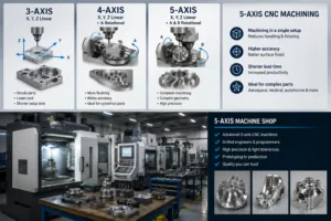
It is also the moment to decide process: a part needing five faces is a different job on a 3-axis machine than on a 5-axis one, and multi-axis machining often removes setups rather than adding cost. The process envelope is set out under CNC machining services.
When should you refuse a DFM suggestion?
DFM advice comes from someone who does not own the design requirement. It is frequently right and sometimes wrong, and a supplier who never says so is selling rather than reviewing.
- When the feature is load-bearing. “Increase this radius” is free on a cosmetic corner and expensive on a fillet sized for fatigue life. If the radius came out of an analysis, say so and keep it.
- When the tolerance came from an assembly stack. Loosening one feature to save machining time can consume the whole stack budget. Tolerances derived from a stack analysis are not over-specification.
- When a standard governs the dimension. An interface defined by a published standard is not negotiable because a cutter would prefer otherwise.
- When consolidation makes the billet enormous. Merging two parts can look elegant and then need a billet three times the size, most of it removed as swarf. Check the stock envelope first.
- When the design is not stable. Optimising a geometry that will change twice more wastes effort on both sides — see our guide to low-volume cost and speed trade-offs.
- When the change moves cost rather than removing it. Eliminating a machining operation by adding a secondary process, an insert or an assembly step may simply move the cost to a different line.
The counter-case runs the other way too: the most expensive DFM failure is not a rejected suggestion but a review skipped because the schedule was tight, followed by a first article that fails on a feature nobody could reach.
Does DFM change as volume increases?
Yes, and the priorities invert. At low volume the dominant cost is work done once — programming, fixturing, first-article verification — so the best changes remove setups and simplify workholding. At production volume the dominant cost is per-part, so the best changes remove seconds from the cycle: fewer tool changes, larger radii allowing higher feeds, less material to remove, less manual deburring.
A change that is worth making at 10,000 parts may be irrelevant at 10, and a change that saves a whole setup is transformative at 10 and merely useful at 10,000. This is why a DFM review should be told the quantity, and why it is worth repeating once a part moves from proving to production — the subject of our guides to scaling across volume tiers and the prototype-to-production cost curve. Early proving batches are usually quoted as CNC prototyping.
Frequently asked questions
How much does DFM actually save on a CNC part?
There is no honest single figure, and any percentage quoted without a named published study behind it is invented. What can be said precisely is where savings come from: fewer setups, larger cutters running faster, fewer toleranced features to verify, less finishing and deburring. The size of the effect depends on how far the starting design was from manufacturable, which is why a review returns specific changes rather than a headline number.
At what stage should a DFM review happen?
Before the drawing is released, and ideally before the geometry is frozen. A change agreed at concept costs a CAD edit; the same change after release costs a revision, a re-quote and possibly re-verification. If a part is already in production, a review is still worth running — legacy drawings frequently carry tolerances inherited from a process that has since changed.
Does simplifying a part for machining reduce its quality?
Handled properly, the opposite. Larger corner radii reduce tool deflection and chatter, improving dimensional consistency and finish; fewer setups remove tolerance stacks between faces; fewer tight tolerances concentrate inspection where it matters. DFM reduces process variation rather than quality.
Can a DFM review be run on parts already in production?
Yes, and it often finds more than a review of a new design, because a legacy drawing accumulates requirements nobody has revisited. The constraint is change control: on a regulated part, any dimensional change may require a partial first article inspection under AS9102, so the saving has to justify the requalification — see our guide to first article inspection in CNC machining.
What is the smallest internal radius I can specify?
Mechanically, whatever a cutter can produce; practically, the question is what it costs. A very small radius forces a very small tool, which is dramatically less stiff, so the cycle lengthens and chatter risk rises. If a sharp internal corner is genuinely required, milling is the wrong process for it and wire EDM is the right one.
How thin can a wall be?
It depends on material, wall height, support and clamping, so no single number is honest. A tall unsupported wall in any material moves under tool pressure. Send the geometry and ask — a reviewer will say where it will deflect and whether a rib solves it.
Does DFM apply to turned parts as well as milled ones?
Yes, with a different checklist: avoid unnecessary undercuts and recesses that require form tools, allow standard tool-nose radii at shoulders, keep the length-to-diameter ratio within what can be supported, and avoid features that require the part to be re-gripped on a finished diameter. Slender turned components are usually a case for Swiss machining rather than conventional turning.
What should I ask a supplier to get a useful review?
Ask three questions: which features force a smaller tool than necessary, which tolerances they would question and why, and where a setup could be removed. Send a model, a drawing, the material and the quantity, then request a CNC machining quote — an engineer responds within 24 hours with the review attached.