An AGV or industrial robot powertrain is the chain of machined parts that turns motor torque into repeatable motion: gear housings, motor mounts, drive shafts, bearing seats, wheel hubs and reducer interfaces. These parts sit inside the load and motion path, so a bore in the wrong place becomes backlash, an oversized bearing seat becomes bearing wear, and a shaft with runout becomes positioning error at the end effector. This article covers what MW+ machines for those platforms, the tolerances that actually govern, how they are verified, and where CNC machining is the wrong process to use.
Key takeaways
- MW+ holds general machined dimensions to ±0.01mm under ISO 2768-m, precision features to ±0.005mm, and critical features to a floor of ±0.001mm, at a process capability of Cpk ≥1.67.
- Bearing seats and shaft journals should be specified as ISO 286-2 fit classes such as H7 or k6, not as a symmetric ± band. The fit class carries the interference the bearing manufacturer actually requires.
- On rotating parts, form controls decide service life more than size does. Specify concentricity, runout and surface texture to ISO 21920-2:2021 alongside the diameter, or the part will pass inspection and still whine in service.
- MW+ surface finish ladder: Ra 3.2µm as-machined, Ra 0.4µm fine-machined, Ra 0.1µm polished. Bearing journals sit at the fine-machined end.
- Lead times: quote within 24 hours, 48-hour express or 3–5 business days for prototypes, 10–15 business days for production. No minimum order quantity, capacity to 1,000,000+ units.
- Every MW+ order ships with a certificate of conformance, a CMM inspection report and material certificates — the traceability an AGV programme needs when the vehicle is assessed against ISO 3691-4.
On this page
- Which powertrain components get CNC machined?
- How tight do robotics powertrain tolerances need to be?
- Why bearing seats need fit classes, not ± tolerances
- What does bore position do to gear backlash?
- Which materials suit AGV and robotics powertrain parts?
- Surface finish, runout and drivetrain noise
- How the parts are verified before release
- Moving from prototype to fleet volume
- When CNC machining is the wrong process
- Frequently asked questions
Which powertrain components get CNC machined?
Six part families cover most of the CNC machining content in an AGV or industrial robot powertrain: gear and reducer housings, motor mounts and adapter plates, drive shafts, wheel hubs and drive wheel cores, bearing seats and retainer plates, and the mounting interfaces for harmonic or cycloidal reducers. Each is defined by a small number of controlled features; everything else on the part is cosmetic or clearance and can be left to a general tolerance class. The wider set of precision parts an automation platform consumes beyond the drivetrain is covered in our note on machine parts for automation equipment.
Use the table below to identify which single feature on each part carries the function, so you know where to spend tolerance and where not to.
| Component | Function in the powertrain | Feature that carries the function | Failure mode when it drifts |
|---|---|---|---|
| Gear or reducer housing | Locates gear centres relative to each other | Bore-to-bore centre distance and parallelism | Backlash, gear whine, uneven tooth wear |
| Motor mount / adapter plate | Aligns servo shaft to gearbox input | Pilot bore concentric to bolt pattern | Misalignment vibration, coupling fatigue |
| Drive shaft | Transmits torque to wheel or joint | Journal diameters, concentricity, straightness | Runout, bearing heating, positional error |
| Wheel hub / drive wheel core | Carries the AGV on the floor | Bore-to-outer-diameter concentricity | Ride vibration, odometry drift |
| Bearing seat / retainer plate | Sets bearing preload and location | Bore fit class and shoulder squareness | Preload loss, premature bearing failure |
| Harmonic or cycloidal reducer interface | Mounts the reducer to the joint structure | Pilot diameter and bolt-pattern true position | Reducer distortion, lost repeatability |
Note what is not on this list: gear teeth themselves. Cutting a gear housing is CNC milling services work. Cutting hardened gear teeth to a quality grade is a gear-shop process, and treating the two as interchangeable is the most common scoping error on robotics drivetrain RFQs.
How tight do robotics powertrain tolerances need to be?
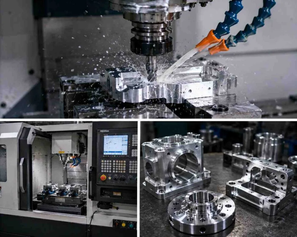
Robotics powertrain tolerances are set feature by feature, not part by part. MW+ holds general machined dimensions to ±0.01mm under ISO 2768-m, precision functional features to ±0.005mm, and critical features to ±0.001mm, all at a process capability of Cpk ≥1.67. What decides which class a feature belongs in is whether an error there shows up as motion error at the output.
Geometric controls matter more than size on most of these parts. A gear housing bore that is 0.01mm oversized is usually harmless; the same bore 0.03mm out of position relative to its partner changes the centre distance and therefore the mesh. Specify that with a true position callout under ISO 1101 or ASME Y14.5, referenced to a datum you can actually locate on the fixture.
| Feature class | MW+ tolerance (mm) | Governing reference | What it protects |
|---|---|---|---|
| Clearance holes, outer profiles, cosmetic faces | ±0.01 | ISO 2768-m general class | Assembly and access only |
| Gear centre distance, pilot diameters | ±0.005 | True position to ISO 1101 or ASME Y14.5 | Gear mesh, coupling alignment |
| Shaft journals, reducer pilots | ±0.001 achievable floor | Fit class to ISO 286-2 | Bearing preload, joint repeatability |
| Mounting face flatness and squareness | Per drawing callout | Flatness and perpendicularity to ISO 1101 | Housing distortion at bolt-up |
Every tolerance you tighten one class costs machine time, inspection time or both. The productive move on a robotics drivetrain is to tighten three or four features and deliberately loosen everything else, rather than applying a uniformly tight blanket tolerance that a quoting engineer has to price defensively. What changes on the shop floor between those classes is compared at 0.01 mm and 0.005 mm.
Why bearing seats need fit classes, not ± tolerances
A bearing seat should be specified as an ISO 286-2 fit class — H7 for a housing bore, k6 or m6 for a shaft journal, for example — because a rolling bearing requires a defined interference or clearance, and that requirement is asymmetric. A symmetric ±0.005mm band around a nominal diameter permits both a loose fit and a heavy press fit, so a part can measure perfectly in tolerance and still destroy the bearing’s internal clearance.
Take the fit class from the bearing manufacturer’s mounting recommendation for the load case, put it on the drawing, and let the machine shop work to it. MW+ machines shaft journals on CNC turning services and housing bores on milling and boring setups, and will hold whichever class the drawing names, but a shop cannot infer the intended interference from a ± band.
What does bore position do to gear backlash?
Backlash is the clearest case of a machined tolerance turning straight into a motion error, so it is worth working once with real numbers.
Step 1, turn the position tolerance into a centre-distance range. Take a housing with two gear bores at a nominal centre distance of 80.000 mm, each bore held to a true position of 0.02 mm diameter against a common external datum. A 0.02 mm diameter zone lets each bore centre sit anywhere within 0.01 mm of its nominal point. In the worst case the two centres move directly apart along the line joining them, so the centre distance varies by 0.01 + 0.01 = 0.02 mm: a range of 79.980 mm to 80.020 mm.
Step 2, turn the centre-distance range into backlash. For a spur or helical pair, a change in centre distance changes backlash by twice that change multiplied by the tangent of the pressure angle. At the 20-degree pressure angle used by the great majority of industrial gearing the tangent is 0.364, so the backlash swing is 2 x 0.020 x 0.364 = 0.0146 mm, call it 0.015 mm.
Step 3, read it against the backlash budget. If the pair is designed to run at 0.05 mm to 0.10 mm of backlash, that 0.015 mm swing has consumed roughly 30 per cent of a 0.05 mm window before tooth thickness tolerance, bearing internal clearance and thermal growth are added. Halve the position callout to 0.01 mm diameter and the swing halves with it, to 0.007 mm.
Step 4, then question the datum. All of that assumed both bores were positioned to an external datum, which is usually the wrong scheme. Position the second bore to the first one as its datum and the common shift drops out of the arithmetic: only the relative position between the two bores is controlled, which is the only thing the gear mesh can feel. The same housing to the same tolerance value then buys a tighter centre distance at no extra cost: a drawing change, not a machining change.
Which materials suit AGV and robotics powertrain parts?
AGV and robotics powertrain parts are machined predominantly from 6061-T6 and 7075-T6 aluminum for housings, mounts and hubs, 4140 alloy steel for drive shafts, and 303 or 304 stainless steel where corrosion resistance or dimensional stability governs. Aluminum is chosen for inertia and machinability, steel for fatigue strength under reversing torque. MW+ machines 70+ material grades, so the constraint is the application, not stock availability.
The values below are nominal published properties for the grade and temper, of the kind held in databases such as MatWeb. Where a property is load-bearing — shaft fatigue, for instance — design against the mill certificate for the actual lot, not against a nominal table.
| Material | Nominal tensile strength (MPa) | Nominal density (g/cm³) | Where it belongs in the powertrain |
|---|---|---|---|
| Aluminum 6061-T6 | ≈310 | 2.70 | Gear housings, motor mounts, adapter plates |
| Aluminum 7075-T6 | ≈572 | 2.81 | Wheel hubs and loaded structural mounts |
| Alloy steel 4140, quenched and tempered | ≈655 | 7.85 | Drive shafts, torque-carrying spindles |
| Stainless steel 304 | ≈505 | 8.00 | Bearing seats and retainers in washdown environments |
| Acetal (POM) homopolymer | ≈70 | 1.42 | Low-load bushings, spacers, idler bodies |
Aluminum and steel are not interchangeable late in a programme. Swapping a 6061-T6 housing to steel changes cutting parameters, cycle time, thermal growth during machining and assembly mass at once, so the swap invalidates both the quote and the dynamic model the controller was tuned against.
Surface finish, runout and drivetrain noise
Surface texture on a bearing journal or seat controls how the bearing seats and how the oil film behaves, which is why a rough journal shortens bearing life even when the diameter is perfect. Specify surface texture as an Ra value on the features that rotate or slide, and leave the rest as-machined. Check which standard the drawing invokes: ISO 4287:1997 has been withdrawn in favour of ISO 21920-2:2021, and drawings in circulation still use either convention, so the title block has to state which one governs. Ra is a parameter, not a finishing process, so name the number rather than a shop-floor description.
| Finish level | Surface roughness Ra (µm) | Typical use on a robotics powertrain |
|---|---|---|
| As-machined | 3.2 | Housing exteriors, clearance pockets, mounting faces |
| Fine-machined | 0.4 | Bearing seats, shaft journals, reducer pilot diameters |
| Polished | 0.1 | Dynamic seal running surfaces |
Runout is the other half of the problem. Total runout on a shaft’s journals relative to its own bearing datums determines the vibration the drivetrain injects into the chassis, and on an AGV that vibration eventually shows up as odometry drift. Call out total runout explicitly; it does not follow automatically from a tight diameter tolerance.
How the parts are verified before release
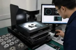
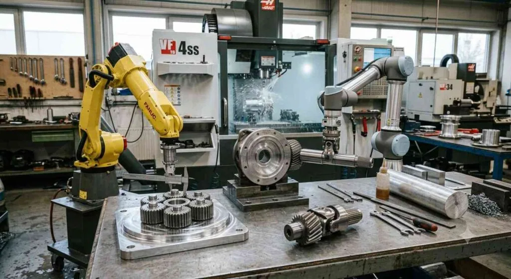
Every MW+ order ships with a certificate of conformance, a CMM inspection report against the CAD model and material certificates for the stock lot. First article inspection to AS9102 and PPAP Level 3 are available on request and quoted per programme. MW+ is certified to ISO 9001:2015, AS9100D, ISO 13485, IATF 16949 and NADCAP.
For an AGV programme that documentation is not paperwork for its own sake. ISO 3691-4 sets safety requirements for driverless industrial trucks and their systems. It applies to the vehicle rather than to any individual machined part, but it is the reason AGV integrators ask for traceable material certificates and inspection records on drive components — the vehicle-level assessment has to rest on something.
Measurement traceability
An inspection report is only as good as the instrument behind it. Gauges and coordinate measuring machines should trace to national standards of the kind maintained through NIST calibration services or an equivalent national metrology institute. The CNC machining quality control process covers how characteristics are captured and reported.
Ask for the awkward measurement
On a first article, ask specifically for the measurement that is hardest to take — bore-to-bore centre distance on a housing, or total runout on a shaft between its own journals. A supplier who reports those without being chased is measuring the part properly rather than measuring what is convenient.
Moving from prototype to fleet volume
MW+ returns quotes within 24 hours and delivers prototypes in 48-hour express or 3–5 business days as standard, with production runs in 10–15 business days. There is no minimum order quantity and capacity extends to 1,000,000+ units, so an AGV programme can take one drive shaft for a test rig and later order a fleet’s worth from the same setup. What sets the gap between a prototype build and a production lot is broken down in our comparison of prototype and production lead times.
That continuity matters more on drivetrains than on structural parts. Requalifying a new supplier mid-programme means a new fixture, a new datum interpretation and a new measurement setup, and the resulting shift is exactly the kind that shows up as a change in drivetrain noise rather than as a failed dimension. MW+ operates a 15,000 m² facility in Guangming, Shenzhen, founded in 2015, with 60+ machining centres and 120+ engineering and quality professionals serving 50+ countries.
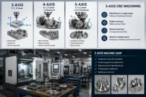
Where a part combines a turned journal with milled features on the same axis, ask whether it can be produced in one setup with multi-axis machining. Every setup removed is a re-fixturing error stack removed, and on rotating parts that stack lands directly on concentricity.
When CNC machining is the wrong process
CNC machining is the wrong process for a robotics powertrain part when the part is a catalogue item, when its function lives in a tooth form rather than a bore, when annual volumes are high enough for a net-shape process to amortise its tooling, or when the feature is a plain low-load spacer. Machining everything is a common and expensive default on early robotics programmes.
| Situation | Better route | Why |
|---|---|---|
| Harmonic drive or planetary reducer needed | Buy the catalogue unit | Rated, tested and cheaper than any bespoke equivalent |
| Hardened gear teeth to a defined quality grade | Gear shop: hobbing, shaping, tooth grinding | Tooth form is a gear-cutting process, not a milling one |
| High annual volume, geometrically simple housing | Die casting or sintering, machining only critical features | Tooling amortises; machine only the bores that matter |
| Low-load bushings, spacers, cable guides | Injection moulding or stock bar | The machining cost exceeds the part’s functional value |
| Flat brackets and covers with no tolerance content | Laser cutting and forming | No milled feature is doing any work |
| Design still changing weekly during control tuning | Machine only the interface parts, print the rest | Do not buy tolerance on geometry that will change |
The honest version of the sourcing conversation is that a good machining partner should tell you which parts on your bill of materials do not need machining. MW+ approaches machine parts manufacturing for automation equipment on that basis rather than pricing every line on a drawing package.
Frequently asked questions
Why did my gear housing pass inspection but still produce backlash?
A gear housing can pass a diameter check and still produce backlash because backlash is governed by the distance between bore centres, not by either bore’s size. If the drawing controls only diameters, the centre distance is uncontrolled and can drift within the sum of the position tolerances. Add a true position callout to ISO 1101 or ASME Y14.5 on both bores, referenced to a common datum.
Should I specify a bearing seat as ±0.005mm or as H7?
Specify it as H7, or whichever ISO 286-2 class the bearing manufacturer’s mounting data calls for. A ± band is symmetric and a bearing fit is not: the same ±0.005mm window permits both a loose seat and an interference that closes the bearing’s internal clearance. The fit class communicates the intent; the ± band only communicates a size.
Can MW+ cut gear teeth as well as gear housings?
MW+ machines gear housings, shafts, hubs, mounts and reducer interfaces. Cutting hardened gear teeth to a defined quality grade is a specialist gear-shop process using hobbing, shaping and tooth grinding, and it is scoped separately from prismatic and turned machining. Ask any supplier to state plainly which side of that line their quote sits on before you award the package.
What tolerance can MW+ actually hold on a drive shaft journal?
MW+ holds precision features to ±0.005mm and critical features to a floor of ±0.001mm, at Cpk ≥1.67 on controlled characteristics. On a drive shaft the useful specification is a fit class on each journal plus a total runout callout between them, because concentricity between journals is what the bearings actually experience.
How fast can I get a single prototype drive shaft?
MW+ delivers prototypes in 48-hour express or 3–5 business days as standard, with a quote returned within 24 hours, and applies no minimum order quantity. Production runs follow in 10–15 business days. Send STEP or IGES geometry with a 2D drawing carrying the datum scheme; MW+ accepts STEP, IGES, DXF, DWG, SolidWorks and PDF.
Does an AGV drive component need certification of its own?
No. ISO 3691-4 applies to the driverless industrial truck and its systems, not to an individual machined bracket, housing or shaft. What the machined part contributes is evidence: a certificate of conformance, a CMM report and material certificates that let the integrator support the vehicle-level assessment. MW+ supplies those with every order.
Why does my quote change so much when I tighten one dimension?
Tightening a dimension past a shop’s routine class usually adds a finishing pass, a slower feed, an extra inspection step, or all three, and it raises the scrap risk on every part. A tolerance that costs nothing at ±0.01mm can cost a separate operation at ±0.005mm. Tighten only the features whose error reaches the output motion, and say so on the drawing.
What should I send with an RFQ for robotics powertrain parts?
Send 3D geometry, a 2D drawing with the datum scheme and functional tolerances, fit classes for every bearing interface, Ra callouts on rotating surfaces, material and temper, annual volume and the documentation level required. If you want a review of which features are actually driving the price, request a CNC machining quote and ask for that review alongside it.
Gear housings, drive shafts and bearing seats for AGV and robotics powertrains are the same families we hold as standing work; each one is listed with its material and process route under our custom machine parts.