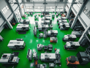
Geometry drives CNC part cost through four physical mechanisms, not through a vague notion of difficulty. Every feature on a model either lets the shop use a big, stiff tool at a high feed rate, or forces a small tool, a long reach, a light cut or an extra setup. Price follows directly from which.
This article traces that mechanism feature by feature, so you can look at your own model and see where the money is going before you send it out to quote.
Key takeaways
- Geometry costs money through four mechanisms: smaller tools, longer tool reach, lower part rigidity, and more setups. Every feature acts through one of them.
- An internal corner radius sets the maximum tool diameter that can reach the corner. The tool diameter then sets the feed rate for the whole pocket.
- Cavities above a 4:1 depth-to-diameter ratio need long-reach tooling, reduced feeds and a chip evacuation strategy.
- Features compound. A thin wall at the bottom of a deep pocket with a tight tolerance is three mechanisms in one location, not three separate additions.
- Specify ±0.01mm to ISO 2768-m as the drawing default and reserve ±0.005mm for features that mate, seal or locate.
- MW+ quotes within 24 hours, ships express prototypes in 48 hours, standard prototypes in 3–5 business days, and volume production in 10–15 business days.
- What makes a CNC part complex?
- The four mechanisms that turn geometry into cost
- Which design features drive up cost the most?
- Why does an internal corner radius change the price so much?
- Worked example: what one corner radius does to pocket cycle time
- Where tolerance and geometry multiply each other
- Does 5-axis machining make a complex part cheaper?
- When simplifying the geometry is the wrong move
- What to send so a complex part is quoted accurately
- Complex part machining at MW+
- Frequently asked questions
What makes a CNC part complex?
A complex CNC part is one whose geometry forces the machine to work below its efficient operating point — through restricted tool access, long tool overhang, low workpiece rigidity, or the need for several tool orientations. Complexity is not size. A 20mm medical component with deep pockets and 0.5mm walls is harder to machine than a 400mm bracket with through-holes and flat faces.
Complexity is counted in setups, not in features
The most useful complexity metric on a model is the number of distinct directions a tool must approach from. Every direction is either an extra setup on a 3-axis machine, or an extra orientation on a 5-axis machine. Both cost time; the setup costs more, because it also adds a re-fixturing error that has to be absorbed by your tolerance.
Count approach directions before you count features. Thirty holes drilled from one face is a simple part; six features approached from six directions is a complex one, whatever the feature count says.
The four mechanisms that turn geometry into cost
Material removal rate is the volume of metal a machine removes per minute, and it is the quantity every geometry decision ultimately moves. A feature raises cost only if it reduces material removal rate, adds a setup, or adds an operation. The table below maps each mechanism to the geometry that triggers it.
| Mechanism | Geometry that triggers it | What the shop must do | Effect on the quote |
|---|---|---|---|
| Smaller tool diameter | Small internal corner radii, narrow slots, small holes | Use a tool that fits the smallest feature, at its feed limit | Whole pocket runs at the small tool’s feed rate |
| Longer tool reach | Deep cavities, recessed faces, features behind walls | Extend the tool, reduce depth of cut, manage chatter | More passes for the same volume of metal |
| Low workpiece rigidity | Thin walls, tall ribs, slender shafts, unsupported bosses | Lighter cuts, extra fixturing or support, sometimes a stress-relief step | More passes and additional fixture cost |
| More setups or orientations | Features on several faces, undercuts, compound angles | Re-fixture, re-datum, re-prove the program | Setup time per batch plus a positional error budget |
The fourth mechanism is the one buyers underestimate. Setup cost is charged per batch, not per part, so it dominates prototype and low-volume pricing and fades at high volume. That is why the same model can be expensive at 10 pieces and reasonable at 1,000.
Which design features drive up cost the most?
The features that drive up CNC cost most are deep cavities, small internal corner radii, thin walls, undercuts and sub-millimetre holes. Each of them acts through one of the four mechanisms above, which is why each has a specific design change that removes the cost rather than a general instruction to simplify.
| Feature | Mechanism it triggers | Design change that removes the cost |
|---|---|---|
| Cavity deeper than 4:1 depth to diameter | Long tool reach | Open the top of the cavity, or step the depth so a shorter tool clears most of it |
| Sharp internal corner | Small tool diameter | Add a radius of at least 0.5 mm, larger if the pocket is deep |
| Wall thinner than 0.5 mm | Low rigidity | Thicken the wall, or add a rib that supports it during cutting |
| Undercut or internal groove | Extra orientation, special tooling | Redesign for side access, or split into two parts and join |
| Hole below 1 mm diameter | Small tool, breakage risk | Increase the diameter, or move the feature to EDM |
| Sculpted 3D contour | Extra orientations, long programs | Reduce the number of unique tool orientations, not the surface quality |
| Ra 0.4µm on all faces | Extra operation per face | Apply the fine finish only to the faces that seal or slide |
| Tight tolerance across a long span | Rigidity and thermal effects | Split the requirement into local features with their own datums |
Feature effects compound rather than add. A thin wall at the bottom of a deep pocket with a tight tolerance on its face is not three separate cost items — it is one location where the tool is long, the material is flexible and the acceptance band is narrow at the same time. Look for these clusters first; they are where the leverage is.
Why does an internal corner radius change the price so much?
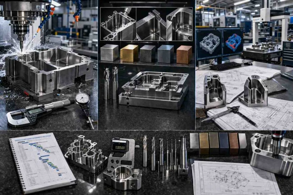
An internal corner radius sets the largest cutter that can reach into the corner, because a milling cutter can only produce a corner as sharp as its own radius. That cutter then has to machine the whole pocket, so a 1 mm corner radius forces a 2 mm cutter across the entire feature, at the feed rate and depth of cut a 2 mm cutter can survive.
This is the highest-leverage single change on most models. Opening a corner radius rarely changes the part’s function, and it lets the shop swap a fragile small cutter for a stiff larger one.
Matching corner radius to pocket depth
The radius and the depth have to be considered together. A cutter’s usable overhang is limited by chatter, and cavities above a 4:1 depth-to-diameter ratio already need reduced feeds. Specifying a small radius in a deep pocket means asking for a thin tool at a long reach, which is the worst combination available.
The practical approach on a deep feature is to scale the corner radius with depth so that a cutter with a sensible length-to-diameter ratio can reach the bottom. Where the corner truly must be sharp — a square key seat, a mating spline — the correct answer is not a smaller cutter but wire EDM services, which produce genuinely sharp internal corners with no cutting force.
Worked example: what one corner radius does to pocket cycle time
Material removal rate makes the corner radius argument concrete. MRR = axial depth of cut × radial width of cut × feed rate, so the cutter diameter sets all three at once. Take a rectangular pocket 60 mm × 40 mm × 20 mm deep in aluminium: 60 × 40 × 20 = 48,000 mm³ of metal to clear. The cutting figures below are stated as assumptions; substitute the numbers your shop actually runs.
- Open corners, 3 mm radius. A 3 mm corner radius accepts a 6 mm diameter cutter. Assume axial depth 6 mm, radial width 3 mm and feed 1,200 mm/min.
- Removal rate with the 6 mm cutter. 6 × 3 × 1,200 = 21,600 mm³/min, so 48,000 ÷ 21,600 = 2.2 minutes of roughing.
- Tight corners, 1 mm radius. The largest cutter that now reaches the corner is 2 mm. Assume axial depth 2 mm, radial width 1 mm and feed 600 mm/min, because chip load per tooth scales with diameter.
- Removal rate with the 2 mm cutter. 2 × 1 × 600 = 1,200 mm³/min, so 48,000 ÷ 1,200 = 40 minutes if that cutter clears the whole pocket.
- Apply rest machining, which is what a real program does. Rough about 90% of the volume with the 6 mm cutter: 43,200 ÷ 21,600 = 2.0 min. Clear the remaining 4,800 mm³ of corner material with the 2 mm cutter: 4,800 ÷ 1,200 = 4.0 min.
- Compare the honest totals. 2.0 + 4.0 = 6.0 minutes against 2.2 minutes, about 2.7 times the cycle for the same pocket and the same finished dimensions.
The 18:1 gap in step 4 is what a naive program produces; the 2.7:1 gap in step 6 is what a competent shop quotes. Either way the corner radius is the only input that changed. Two caveats: a 2 mm cutter at that depth may also need a longer reach, which cuts the assumed feed further, and on a shallow pocket the gap narrows because there is less corner volume to clear.
Where tolerance and geometry multiply each other
A tolerance is cheap or expensive depending on where it sits. The same ±0.005mm band is routine on a short, well-supported feature machined in one setup, and difficult on a thin wall, across a long span, or between two features that are cut in different setups. Geometry decides which case you are in.
Set the drawing default at the general tolerance class in ISO 2768 and mark tighter values individually. Where a fit is what matters, specify the ISO 286 fit designation rather than a symmetric band — the limits and fits system is defined in ISO 286. Where form or position is what matters, use the geometrical tolerancing symbols in ISO 1101 or their ASME equivalents in ASME Y14.5, which frequently gives the shop more usable tolerance for the same functional result.
| Tolerance level | Achievable on | Typical use | Geometry that makes it expensive |
|---|---|---|---|
| ±0.1 mm | Any feature, any setup | Clearance holes, cosmetic edges | Nothing — leave it at the drawing default |
| ±0.01 mm to ISO 2768-m | Most features in a single setup | General machining default at MW+ | Long unsupported spans |
| ±0.005 mm | Rigid features, one setup, controlled temperature | Bearing seats, sealing bores, locating faces | Thin walls, deep features, cross-setup dimensions |
| ±0.001 mm | Short, rigid, well-supported features | Critical fits on precision components | Anything measured across a setup boundary |
MW+ holds general machining to ±0.01mm to ISO 2768-m, applies ±0.005mm where a feature requires it, and reaches a ±0.001mm floor on CNC precision parts where geometry allows. Surface roughness, defined as Ra in ISO 21920-2:2021, which replaced ISO 4287,, behaves the same way: Ra 3.2µm as-machined is included, and every step below is an operation.
Does 5-axis machining make a complex part cheaper?
5-axis machining makes a complex part cheaper when it removes setups, and more expensive when it does not. A part needing four separate 3-axis setups may run complete in one 5-axis setup, which removes three re-fixturings and the positional error each introduces. A prismatic part that already runs in one 3-axis setup gains nothing from a 5-axis machine and simply pays the higher machine rate.
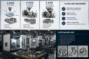
| Criterion | 3-axis | 4-axis | 5-axis |
|---|---|---|---|
| Tool approach | One direction per setup | Rotation about one axis | Any direction within the machine envelope |
| Best suited to | Prismatic parts, flat faces, through features | Parts with features around a cylinder | Compound angles, sculpted surfaces, multi-face parts |
| Setups for a six-face part | Up to six | Two to three | Often one or two |
| Positional error between faces | Accumulates across setups | Reduced | Lowest — features share one datum |
| Machine hour rate | Lowest | Middle | Highest |
| Cheapest when | The part already runs in one or two setups | Features are arranged radially | The alternative is four or more setups |
The decision rule is simple: count the setups each route needs, not the axes. If a redesign of two features would let the whole part run on a 3-axis machine, that redesign is usually worth more than the 5-axis capability. Where it is not, multi-axis machining earns its rate by collapsing the setup count.
When simplifying the geometry is the wrong move
Simplifying geometry is the wrong move whenever the complexity is doing work. A monolithic part that is expensive to machine can still be cheaper than the assembly that replaces it, once fasteners, joints, sealing and assembly labour are counted. And some features exist because a qualification or a regulation put them there.
| Situation | Recommendation | Why |
|---|---|---|
| The feature is a sealing or fluid path | Keep the geometry | A leak path costs more than the machining ever will |
| Simplifying means splitting into an assembly | Cost the assembly first | Fasteners, joints, sealing and assembly labour often exceed the saving |
| Weight is the design driver | Keep thin walls and pockets | The pocketing is the point; buy rigidity with fixturing instead |
| The part is qualified or in production | Do not change the geometry | Requalification and PPAP resubmission exceed the machining saving |
| Prototype quantities only | Do not optimise yet | At low volume setup dominates; optimise geometry when volume justifies it |
| Corners must genuinely be sharp | Keep them, change the process | EDM produces sharp internal corners that milling cannot |
| Features are below about 1 mm | Keep them, change the process | Micro-machining and EDM are built for this scale |
The last two rows point at the same principle. When geometry is genuinely required, the answer is a process that suits it — micro machining services for very small features, EDM for sharp corners and hardened material — rather than a compromise on the design.
What to send so a complex part is quoted accurately
- A 3D model in STEP or IGES, plus a drawing. The model carries the geometry; the drawing carries the requirements.
- A general tolerance class in the title block, with tighter values marked only on features that mate, seal or locate.
- Datums that reflect how the part is used, so the shop can align its fixturing with your functional reference.
- The quantity and the expected annual volume, because setup amortisation changes the answer completely.
- A note saying which features are negotiable, so the supplier can propose a design change instead of quoting around it.
The last point does most of the work. A supplier who knows a radius is open will tell you what opening it saves; one who assumes every dimension is fixed quotes the hardest interpretation. Ask for that feedback when you request CNC milling services.
Complex part machining at MW+
MW+ is a precision CNC machining supplier operating a 15,000 m² facility at No. 39 Xishi Road, Hewan Community, Guangming, Shenzhen, founded in 2015, with 120+ engineering and quality professionals, 60+ CNC machining centres and 70+ material grades, serving customers in 50+ countries with no minimum order quantity and volumes to 1,000,000+ units.
MW+ returns quotes within 24 hours with a review of the geometry features that are setting the price. Express prototypes ship in 48 hours, standard prototypes in 3–5 business days, and volume production runs in 10–15 business days. The CNC machining capabilities list covers the machine and process mix, including the low-volume prototyping route.
Every MW+ order ships with a certificate of conformance, a CMM inspection report and material certificates, under a quality system certified to ISO 9001:2015, AS9100D, ISO 13485, IATF 16949 and NADCAP, with process capability held at Cpk ≥1.67. First article inspection to AS9102 and PPAP Level 3 are available on request, quoted per programme. Send a model and drawing in STEP, IGES, DXF, DWG, SolidWorks or PDF to request a CNC machining quote.
Frequently asked questions
Why did my quote go up when I only changed one corner radius?
Because an internal corner radius sets the largest cutter that can reach the corner, and that cutter then machines the whole pocket. Reducing the radius from 3 mm to 1 mm forces a 2 mm cutter in place of a 6 mm one, and the smaller cutter runs at a lower feed rate and a shallower depth of cut for the entire feature, not just the corner.
Is a 5-axis part always more expensive than a 3-axis equivalent?
No. The 5-axis machine hour rate is higher, but the comparison that matters is total setups. A part needing four 3-axis setups can be cheaper in one 5-axis setup once handling, re-fixturing and the extra inspection those setups require are counted. A part that already runs in one 3-axis setup is always cheaper on the 3-axis machine.
Why is my prototype price so much higher per part than production?
Setup, programming and first-article inspection are charged per batch rather than per part, so at ten pieces they dominate and at a thousand they almost disappear. Complex geometry raises the setup component specifically, which is why a complex part shows a much steeper price curve between prototype and production quantities than a simple one.
Can I keep the geometry and reduce cost another way?
Yes, usually through tolerance and finish rather than shape. Moving non-critical features from a blanket tight band to the ISO 2768-m general tolerance, and restricting fine surface finish callouts to the faces that seal or slide, removes finishing passes and inspection points without touching the model. Both levers are worked through in budgeting for a tight tolerance and in specifying surface finish in Ra. Stock form is the third: a blank closer to the finished envelope removes cutting time.
How thin can a wall be before it becomes a problem?
Walls below about 0.5 mm start to deflect under cutting load, which forces lighter passes, extra support and sometimes a stress-relief step between roughing and finishing. The height-to-thickness ratio matters as much as the absolute thickness: a short 0.5 mm rib behaves very differently from a tall one. Adding a supporting rib is often cheaper than thickening the wall.
How does material choice change the cost of complex geometry?
Material multiplies the geometry penalty rather than adding to it. A deep pocket that needs reduced feeds in aluminum needs reduced feeds, pecking and more frequent tool changes in stainless steel, so the same geometry costs more in the harder grade. If the load case allows a more machinable grade, that change reduces the cost of every difficult feature at once, which is the first move in any material cost review.
Geometry sets price through tool size, tool reach, part rigidity and setup count. Look at your model for the places where two or three of those act together, decide which of them your design genuinely needs, and open the rest. That is where the cost is, and it is nearly always recoverable before the first quote.