







Choose between CNC machining and 3D printing by what the functional prototype must demonstrate, then compare the actual material, geometry, finished condition and verification route. CNC removes material from stock; additive manufacturing builds a part in layers. Those process definitions do not by themselves establish which prototype will answer your engineering question. [1] [4]
This guide explains how to choose CNC machining or 3D printing for functional prototypes without assuming a universal winner. It includes a requirements comparison and an original numeric cost example. All example dimensions and costs are hypothetical. No example represents a supplier quote, measured prototype or completed MetalWorksPlus customer project, and the process comparison does not imply that MW+ offers every printing technology discussed.
Contents
CNC machining vs 3D printing: start with the test
Write the prototype’s question before selecting a manufacturing route. Examples include whether a housing fits its mating equipment, whether an assembly can be installed with the intended tools, whether a specified material tolerates the planned environment, or whether a sealing interface meets an approved test. Give each question an acceptance criterion and a named decision owner.
A useful engineering recommendation is to separate appearance, assembly fit and functional performance into different requirements. One prototype may answer several questions, but record which conclusions its evidence supports. If the material is deliberately substituted for an early access trial, disclose that substitution in the test record rather than allowing the trial to become material qualification.
Formlabs documents both concept exploration and functional prototyping applications for its printing systems. [2] That is a reason to evaluate a suitable printed route rather than dismiss it by category. It is not evidence that any printed material can replace the specified production grade under every load, temperature or chemical condition.
Likewise, request evidence for a proposed machined prototype instead of treating the word CNC as qualification. Identify stock grade, condition, finished geometry and the inspection plan. The selection decision should connect a reproducible test to a documented part, regardless of which process supplies it.
Subtractive vs additive manufacturing: compare actual routes
Replace broad labels with the proposed operation sequence. Protolabs Network distinguishes CNC stock removal from layer-based printing and describes different manufacturing and post-processing workflows. [1] In the RFQ, name the printing method and material or the machining stock and intended operations, then require the supplier to identify the delivered condition.
For this review, treat a route as the entire sequence through inspection and delivery. Ask what preparation, supports or fixtures are proposed, which finishing steps are included, and when dimensional acceptance occurs. These questions are our recommended comparison method; they do not impose a single sequence on all printing or machining processes.
| Question to resolve | CNC route: request this evidence | Printed route: request this evidence |
|---|---|---|
| What material is being evaluated? | Specified stock grade, condition and traceable material record | Specified feedstock, process and final condition; applicable property evidence |
| Can the geometry be delivered? | Tool and workholding access review for the actual model | Build arrangement, relevant support/removal plan and access review |
| Which interfaces must fit? | Released dimensions, datums, finish stage and inspection coverage | As-built versus finished requirements and any secondary machining |
| What will the test establish? | Named test, specimen/component identity and acceptance criteria | The same test question, with process/material differences disclosed |
| What does the quotation include? | Preparation, manufacture, finishing, inspection and delivery | The equivalent complete scope, including any secondary operations |
CNC or 3D printing prototype: define the proposed route
Formlabs presents SLA and SLS among its prototyping options, while Protolabs Network discusses additional polymer and metal routes. [1] [2] Ask which specific process is proposed and review that process’s applicable material documentation. Avoid evaluating a metal powder-bed route using assumptions taken from an unrelated filament or resin example.
For a CNC or 3D printing prototype enquiry, send the same controlled model revision and functional requirements to each candidate route. Permit route-specific proposals, but require them to identify every deviation. This keeps the comparison traceable when one proposal changes the material, splits the part or introduces a secondary operation.
Functional prototyping requires material evidence
Material names are not a complete test description. Request the exact designation, relevant condition and evidence applicable to the proposed process. Where the property controls the decision, identify the test method, specimen orientation, conditioning and final treatment behind the supplied data. Compare the evidence before assigning a property value to the prototype model.
NIST’s 2021 study of electron-beam powder-bed-fused Ti-6Al-4V examines specimen geometry and discusses the difficulty of comparing studies that combine different geometries, finishing and post-processing. Its abstract also identifies prior observations of build-orientation differences. [3] This is a specific research context, not a strength-reduction factor for all printed parts.
Our recommendation is to retain the evidence chain from material and process definition to the tested configuration. If a supplier provides a tensile coupon result, ask how it relates to the actual prototype and test question. Document any gap rather than treating a coupon result, catalog label and finished component as interchangeable evidence.
State what a substitute prototype cannot prove
Suppose the immediate objective is to check installation access, while the final design requires a different material for service. A substitute prototype may be proposed for that limited access trial. Record the substitute, the approved trial scope and the deferred material questions. Do not describe a successful installation as proof of service strength or environmental suitability.
For a later functional trial, reconsider the requirements using the actual material and process proposal. Ask the responsible engineer which earlier observations remain relevant and which must be repeated. This preserves the value of early prototypes without carrying unsupported conclusions into release.
Review access, interfaces and the finished condition
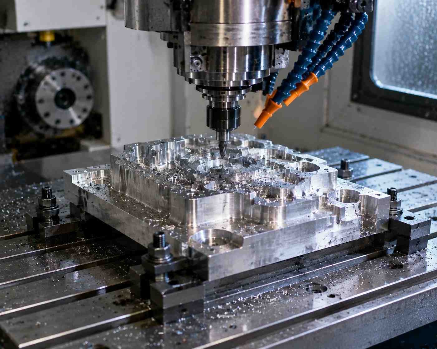
Protolabs’ CNC guide describes removing material from block or rod and reviewing features such as holes, walls and access. [4] Use that principle to request an actual manufacturability review. Identify the surfaces the tool must reach and how the component will be held; do not import another supplier’s dimensional rules as universal limits.
For the printed proposal, request the build arrangement and the treatment of features that need final acceptance after any finishing. Protolabs Network describes combining printed geometry with machining of critical features. [1] A hybrid route deserves its own review of locating references, machining access and finished requirements; it is not automatically qualified because both processes are available.
Define the final dimensional question
As an illustrative drawing exercise, assume a bore requirement of 8.000 ±0.020 mm. Its limits are 7.980 and 8.020 mm. An invented reading of 8.035 mm is 0.015 mm above the upper numerical limit. This is arithmetic using hypothetical inputs, not a measured result or a capability statement about either process.
The example identifies a question for the inspection plan: what exactly is measured, in which state, by which method and under what acceptance rule? A real disposition must account for the applicable geometry, measurement uncertainty and agreed decision rule. Do not replace that review with a generic process-accuracy chart.
Separate shape approval from drawing approval. If a proposed route alters an internal corner, divides a component or changes a finish stage, ask the designer to approve the resulting definition before manufacture. Keep the original and revised requirements distinguishable so that any later test result has a clear configuration reference.
Compare complete-route cost using explicit assumptions
Use current, scope-matched quotations for an actual procurement decision. The following deliberately simplified model explains setup amortization only. It contains no market prices, supplier offers, delivery claims, scrap rates or test results. Neither assumed route is preferred until it also satisfies the technical requirements.
Assumed cost inputs: Define an illustrative currency unit, CU. Let a CNC route have a fixed preparation cost of 300 CU and a variable cost of 30 CU per part. Let a printed route have a fixed preparation cost of 60 CU and a variable cost of 60 CU per part. Assume one unchanged design, all requested parts supplied, and identical included scope. Total cost is C = F + vQ, where Q is quantity.
| Assumed quantity Q | CNC total, CU | CNC per part, CU | Printed total, CU | Printed per part, CU |
|---|---|---|---|---|
| 1 | 330 | 330 | 120 | 120 |
| 5 | 450 | 90 | 360 | 72 |
| 10 | 600 | 60 | 660 | 66 |
| 20 | 900 | 45 | 1260 | 63 |
The algebraic crossover in this invented model is 300 + 30Q = 60 + 60Q, giving Q = 8. Both totals are then 540 CU, or 67.5 CU per part. Changing either assumed preparation or variable cost changes that result. There is no basis for adopting eight parts as a universal process-selection boundary.
For a real comparison, ask each supplier to itemize the relevant scope, revision assumptions and validity period. Include any required material evidence, secondary machining, finishing, inspection and delivery. When the designs or acceptance scopes differ, resolve that difference before comparing totals. Keep schedule evaluation separate, using the actual proposed sequence and availability rather than an invented universal lead time.
Plan a prototype that produces useful evidence
Before ordering, make a short validation plan linking each engineering question to the evidence needed. Identify the test article, configuration, method, acceptance criterion and decision owner. If one part is consumed or altered during testing, account for that use when determining the required quantity. Do not assign a universal sample size from this article.
Record actual observations and distinguish them from interpretations. A successful fit trial documents that trial’s configuration and conditions. Any conclusion about other materials, process routes, quantities or service conditions requires an explicit engineering basis. Mark unanswered questions so that an early prototype does not acquire an unsupported production-release status.
When revising the model, retain the tested revision and explain which requirement changed. Ask whether the change affects the earlier evidence and which checks need repeating. This is particularly useful when moving between a printed concept, a machined functional prototype and a later production route.
Process-selection checklist and next step
- Question: What must the prototype demonstrate, and what remains outside its scope?
- Material: Which designation, condition and applicable property evidence are required?
- Geometry: Which interfaces and access constraints need approval?
- Route: What preparation, finishing and inspection define the delivered part?
- Cost and timing: Are current proposals based on the same revision and acceptance scope?
- Evidence: Which records connect the manufactured configuration to the test decision?
For the machining option, discuss the controlled features within MW+’s precision component range. Use the CNC prototyping discussion for the proposed test article, then the machining service review to clarify the manufacturing route. Send MetalWorksPlus the released model, drawing, material definition and inspection requirements. Confirm any additive or hybrid scope separately.
Frequently asked questions
Is CNC machining vs 3D printing mainly a price decision?
Start with the required engineering evidence. A cheaper prototype is not an equivalent offer when its material, geometry or test scope differs. Compare complete technical proposals before selecting from current quotations.
Can a printed part be a functional prototype?
Yes, appropriate printed routes are used for functional prototyping, as Formlabs documents. [2] Suitability still needs to be established for the specific material, process and test conditions; the category alone is not qualification.
Does machining guarantee production-equivalent properties?
Do not assume it. Identify the stock, condition, drawing and process definition, then decide which conclusions the trial supports. A prototype made to a different material or configuration should retain that limitation in its record.
Can a printed component have machined interfaces?
Protolabs Network describes combining additive geometry with secondary machining of critical features. [1] Review the proposed locating references, access and finished requirements for the actual hybrid route.
How to choose CNC machining or 3D printing for functional prototypes?
Define the test, establish material evidence, review geometry and final condition, compare complete-route proposals, and retain traceable validation records. The cost and dimension examples here explain arithmetic; they approve no physical prototype.
Technical references
- Protolabs Network: 3D Printing vs CNC Machining. Subtractive/additive definitions, process-specific workflows and combination of additive geometry with machined features. Vendor tolerance, volume, price and delivery bands not adopted.
- Formlabs: Rapid Prototyping Applications. Documented functional prototyping applications using SLA/SLS; does not establish universal material equivalence or MW+ printing capability.
- NIST: Specimen Geometry and Orientation in Electron Beam Powder Bed Fusion Ti-6Al-4V (2021). Study-specific context for orientation, specimen geometry, finishing and comparability of tensile evidence; no universal numeric material properties inferred.
- Protolabs: Definitive Guide to CNC Machining. Cutting from block/rod, part geometry, hole and tool-access design considerations. Vendor tool limits and capability figures not transferred.
Sources reviewed on 29 October 2026. Selection questions are engineering recommendations. All numerical examples are original assumed-input exercises, not MW+ measurements, quotes, performance improvements or project records.