







Brinell vs Rockwell hardness is a choice about what to measure and where the measurement can be made. Brinell measures the diameter of a ball impression. Rockwell measures the change in indentation depth during a prescribed force cycle. Start with the scale on the drawing or material specification. If you are writing the requirement, choose a scale that suits the material, expected hardness and test surface. [1–3]
For Brinell vs Rockwell hardness on machined parts, first ask whether the result is meant to represent the incoming stock, the finished surface or a hardened layer. Each question can lead to a different test location. As a result, the test method and the place you test should be decided together. [1, 2]
Brinell vs Rockwell hardness: What each method measures
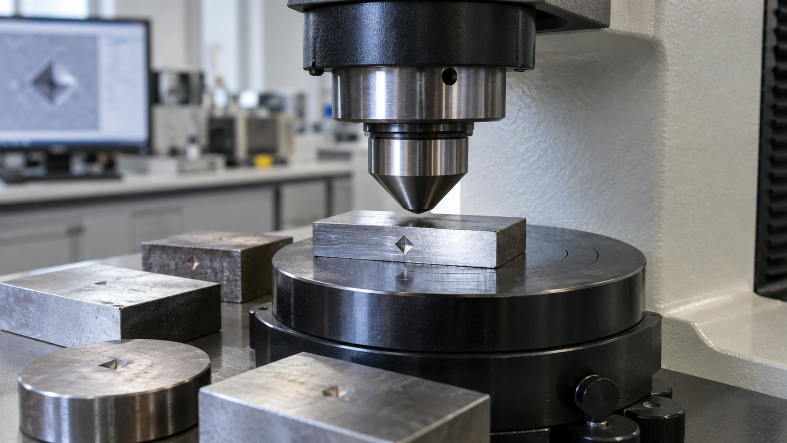
In a Brinell test, a tungsten carbide ball is pressed into the part under a specified force. After unloading, the optical system measures the impression. Brinell hardness, designated HBW, relates the applied force to the curved area calculated from the measured impression and the ball diameter. Consequently, a larger impression under the same ball and force gives a lower hardness number. For a Brinell test near a drawing limit, ask how the laboratory checked the clarity of the impression boundary before accepting the optical reading. [3]
In a Rockwell C test, the diamond indenter establishes a depth reference under a preliminary force. The machine applies the additional force, returns to the preliminary force and measures the difference from the reference depth. Therefore, a smaller permanent depth increase gives a higher HRC reading. [2]
HBW and HRC on an inspection report
The numbers in Brinell vs Rockwell hardness reports are meaningful only with their designations. For example, HBW 10/3000 identifies a Brinell condition with a 10 mm carbide ball and a force historically expressed as 3,000 kilogram-force (kgf). HRC identifies the Rockwell C scale. Its test forces are already defined by the scale. [2, 3]
| Condition | Indenter | Applied force | Reading |
|---|---|---|---|
| HBW 10/3000 | 10 mm tungsten carbide ball | 29.42 kN (3,000 kgf) | Optical impression diameter |
| HBW 5/750 | 5 mm tungsten carbide ball | 7.355 kN (750 kgf) | Optical impression diameter |
| HRC | Spheroconical diamond | 98.07 N preliminary and 1,471 N total (10 and 150 kgf) | Depth difference at preliminary force |
In Brinell vs Rockwell hardness comparisons, the two Brinell settings above are examples of standardized conditions. Changing the ball and force to fit a feature requires checking the applicable method and the drawing. Likewise, the Rockwell total force includes the preliminary force. The two listed forces are stages of one test cycle. [1–3]
Brinell test or Rockwell: Which test fits the part?
If your team is deciding how to choose a hardness test, start with what the result will release. For incoming stock, identify the condition required by the material specification. For release after heat treatment, identify the surface and processing stage named by the drawing. Then check whether the chosen location can support the correct indentation. [1, 2]
Brinell vs Rockwell hardness on a thick casting illustrates the role of footprint. A larger Brinell impression samples a wider area, which can be useful for a relatively coarse or heterogeneous structure. However, a wide impression also needs room from edges and previous marks. The test face must let the operator see and measure the impression boundary. [3]
For Brinell vs Rockwell hardness on a hardened component, a Rockwell C reading may be appropriate if the specified surface, expected hardness, thickness and support suit that scale. For example, inspect the seating of a stepped shaft on the anvil before accepting a measurement from its end face. If the drawing calls out a curved surface, check whether the specified method permits a curvature correction for that geometry. [1, 2]
Thin sections, curved faces and shallow cases
A small feature complicates Brinell vs Rockwell hardness selection. Check the method’s specimen thickness, edge distance and spacing requirements using the actual geometry. Next, confirm the location can be supported without rocking or deflecting. When regular Rockwell is unsuitable, a superficial scale or a different method may be an option if the drawing authority approves it. [1–3]
Similarly, a reading on a hardened surface describes the response at the test location. If the requirement concerns effective case depth or the hardness profile from surface to core, ask for the drawing’s prescribed sectioning and depth-evaluation method. Keep this requirement separate from the surface acceptance range. [1, 2]
In Brinell vs Rockwell hardness planning, also ask whether the prepared surface will still represent the material that must pass. For example, if the specified point is on the hardened face, have engineering agree on any material removal needed to create an acceptable test surface. If grinding stock is still present at inspection, confirm whether the result is for the intermediate part or for release at final size. [1, 2]
Likewise, distinguish a representative coupon from the final part. If the drawing permits a coupon, document the link to the production lot, relevant material condition and heat-treatment batch. For a coupon standing in for a specific location, ask the approving engineer what makes it representative. Brinell vs Rockwell hardness selection cannot resolve a disagreement about the intended specimen. [1, 2]
What a 4 µm depth difference changes on the C scale
For Brinell vs Rockwell hardness, the Rockwell depth relationship explains why setup matters. The NIST practice guide gives the regular diamond-scale equation, HRC = 100 − h / 0.002 mm, where h is the depth difference measured under the preliminary force before and after the total force stage. [2, section 2.4]
Rockwell C test calculation with assumed depths
For this illustration, assume a drawing acceptance range of 49–52 HRC and the three depth differences below. These inputs are hypothetical. First, divide each depth difference by 0.002 mm. Then subtract the resulting dimensionless number from 100. This worked example applies the Rockwell C definition and assumes the measurement itself is valid. [2]
| Assumed depth difference (mm) | Depth divided by 0.002 mm | Calculated reading | Range check |
|---|---|---|---|
| 0.100 | 50 | 50 HRC | Within range |
| 0.104 | 52 | 48 HRC | Below range |
| 0.110 | 55 | 45 HRC | Below range |
As a result, the increase from 0.100 mm to 0.104 mm, or 4 µm, changes the result by two HRC points. In a Brinell vs Rockwell hardness review, use this sensitivity to explain why the inspection plan addresses support, cleanliness and machine verification. The table evaluates hypothetical readings and supplies no estimate of instrument error or production capability. [2]
For example, when a Rockwell C test reading falls below a limit, retain the original result and check whether the instrument verification, specimen support and surface condition were valid. Follow the agreed retest and disposition rules. This gives the quality team a record of what changed between readings. [2]
The corresponding Brinell sensitivity works through diameter. For an illustrative 10 mm ball and 3,000 kgf force, assume an average impression diameter of 3.80 mm. Using the spherical-cap area, A = πD(D − √(D² − d²))/2, gives approximately 11.78 mm² and a calculated value near 255 HBW 10/3000. Here D is the ball diameter and d is the average impression diameter, both in millimetres. The calculation uses the historical kgf form of the HBW equation. It gives no corresponding HRC value. [3]
Therefore, a Brinell vs Rockwell hardness report should retain the method used to obtain each number. A recorded ball size and force help the reviewer interpret an HBW entry. For HRC, the reviewer should be able to identify the scale, specimen and measurement location. Both examples above use assumed inputs for explanation. [1–3]
Write the drawing callout and agree on the inspection record
A hardness specification is useful when the supplier and buyer can point to the same part state, surface, scale and acceptance rule. In a Brinell vs Rockwell hardness review, identify the applicable material condition and revision first. Then mark the allowed test area or approved representative specimen and state when it is measured in the manufacturing sequence. [1, 2]
What to confirm before requesting a quote
- Method and limit. Specify the scale, governing document and acceptance range. For Brinell, identify the ball and force condition when needed.
- Location and surface. Mark a face, zone or approved coupon. State where impressions are permitted and agree how the surface will be prepared and supported.
- Sampling and decisions. Specify whether the limit applies to each result or another agreed basis. Define lot identity and the escalation path for disputed results.
- Records. Request individual readings, test locations, part or lot identity and the procedure used. Identify any approved conversions separately.
For procurement, a Brinell vs Rockwell hardness review can start by sending the drawing with the required inspection stage marked. When deciding how to choose a hardness test for incoming stock, determine the lot that the report must represent. For example, a stock acceptance record may be tied to a heat or material lot. A finished-part record should identify the location tested or document the agreed coupon relationship. Carry those details forward when revisions change the available test surface. [1, 2]
In Brinell vs Rockwell hardness discussions, a supplier may have data on a different scale. ASTM E140 describes scale conversions as approximate and organizes them by material and applicable scale. If a conversion is approved, keep the original method and result, state the conversion basis and clearly label the converted value. For acceptance, use the specified scale whenever practical. [1, 2]
In a Brinell vs Rockwell hardness acceptance plan, give the inspector a location identifier that can be traced back to the drawing. An example is a labelled nonfunctional pad. Similarly, list the instrument and verification record where the inspection plan calls for traceability. If the finish stage or coupon choice changes, have the responsible quality engineer review the setup before using the readings for release. [1, 2]
To discuss a Brinell vs Rockwell hardness callout, share the drawing, test stage and reporting requirement with MetalWorks Plus. Review the production route with CNC machining services, or see the precision parts overview and quality assurance information before discussing the inspection handoff.
Key takeaways
- Use the specified scale and test method for acceptance. Record the test stage and location with the result.
- When comparing Brinell vs Rockwell hardness for a new callout, check material condition, part thickness, surface geometry, support and room for the mark.
- Set separate requirements for surface hardness and case-depth verification when both affect acceptance.
- Retain original measurements and identify any approved conversion and its limits.
References
- ASTM International mechanical testing standards catalog. E10 covers Brinell, E18 covers Rockwell and E140 covers hardness conversion tables. Use the edition specified for the job.
- NIST SP 960-5, Rockwell hardness measurement practice guide. Sections 2.2–2.4 and 3 cover the force cycle, C-scale equation and measurement setup.
- ZwickRoell Brinell method and test conditions. See the indentation principle, examples of ball and force combinations, and specimen guidance.
Frequently asked questions about Brinell vs Rockwell hardness
What belongs in a hardness specification?
Include the governing method and scale, acceptance limits, part condition, test location and sampling. Also agree which individual results and traceability information must be reported. [1, 2]
Can an HBW value be reported as an HRC value?
A permitted estimate needs the applicable material and scale table. Keep the original measurement and clearly identify any conversion. Consequently, a converted number and a direct measurement should occupy separate fields in the report. [1, 2]
Can a shop test on a finished sealing or bearing surface?
Indentation leaves a mark. First, check the drawing for an allowed location. If the functional face must remain intact, request an approved alternate location or representative sample before testing. [2, 3]
Does one reading establish hardness across the whole part?
A reading represents its test location. If a Brinell vs Rockwell hardness decision depends on gradients or different areas of the part, specify which locations require evidence and what method applies to each. [1, 2]