Bearing housing fits define the dimensional relationship between a bearing outer ring and its housing bore. The correct fit is not automatically “H7” or “press fit”: it depends on which ring sees a load that rotates relative to it, the load magnitude and direction, bearing type and size, operating temperature, housing material and stiffness, required axial movement, and assembly method. NTN classifies resultant fits as loose, transition or tight and recommends selecting them from the actual operating conditions. [1]
This application guide works through an 80 mm radial-bearing example and shows how to calculate the full clearance range, not just quote a tolerance class. It is an illustrative engineering study, not an MW+ customer project, production result or universal fit recommendation. The bearing, load case and dimensions must be confirmed with the selected bearing manufacturer before release.
Contents
- What a bearing housing fit controls
- Start with load direction, not a tolerance letter
- Worked example: an 80 mm bearing in an H7 bore
- Compare clearance, transition and interference windows
- Temperature and internal bearing clearance
- Bore geometry, shoulders and housing stiffness
- Machining and inspection plan
- Bearing housing fit checklist
- Frequently asked questions
- Preparing a manufacturing handoff
- Technical references
How bearing housing fits control assembly
A fit is the range of possible clearance or interference after the permitted bearing outside-diameter range is combined with the permitted housing-bore range. NTN notes that relative movement can occur radially, axially or circumferentially at the mating surfaces, and that a tight fit is effective at preventing movement but reduces ease of installation and removal. A tight outer-ring fit can also prevent axial displacement when a non-separable bearing is intended to float. [1]
That means the housing bore tolerance has at least four jobs to support: hold the outer ring against damaging creep where needed, avoid excessive interference, preserve the bearing’s intended operating clearance, and support the locating or floating function of the bearing arrangement. NTN identifies creep and fretting damage, negative internal clearance, noise and loss of rotational accuracy among possible consequences of an improper fit. [1]
Start with load direction, not a tolerance letter
The practical question is whether the radial load direction rotates relative to the outer ring. NTN states that a ring under a rotating load needs a tight fit, while a ring under a static load can use a loose fit; “rotating load” describes the load rotating relative to the ring, not merely a shaft turning somewhere in the assembly. NTN’s general housing table therefore moves from H-type clearance fits for static outer-ring loads toward M7, N7 or P7 as outer-ring load rotation and severity increase. Those recommendations are expressly scoped to the bearing classes and cast-iron or steel housings covered by the table. [1]
| Question | Why it changes the decision | Required evidence |
|---|---|---|
| Does the load rotate relative to the outer ring? | A rotating ring load generally drives the choice toward interference; a stationary ring load can permit clearance. [1] | Load diagram, ring motion and duty cycle |
| Must the outer ring move axially? | A tight fit can block the displacement required at a floating bearing position. [1] | Locating/floating bearing arrangement |
| What are the load magnitude, shock and vibration? | NTN’s fit selection considers load nature and magnitude, speed and temperature; its general table tightens recommendations as duty becomes more severe. [1] | Radial and axial loads, shock case, speed |
| What are the bearing and housing materials? | Different thermal expansion changes the resulting interference as temperature changes. [1] | Material grades and operating temperatures |
| Is the housing thin, split or flexible? | Wall thickness and housing rigidity affect fit selection and ring deformation. [1] [3] | Section geometry, joint condition and clamping state |
Engineering recommendation: put the load diagram, bearing designation and locating/floating function on the fit-review sheet. A bare “80 H7” callout tells a machinist the bore limits, but it does not document why that fit is appropriate for the assembly.
Worked example: an 80 mm bearing in an H7 bore
Assumed application: a Class 0 radial bearing has a nominal outside diameter of 80 mm; its outer ring is stationary relative to a steady radial load; axial displacement at this bearing position is permitted; and the housing is steel or cast iron. These inputs are hypothetical. NTN’s general table lists H7 for a static outer-ring load where axial movement is permitted, but the final selection still belongs to the bearing application engineer. [1]
For a nominal bearing outside diameter over 50 mm through 80 mm, NTN’s numerical table gives a mean outside-diameter deviation of 0 to −13 µm and an H7 resultant fit of 0 to 43 µm loose. The corresponding dimensions are:
- Bearing outside diameter: 79.987 to 80.000 mm.
- H7 housing bore: 80.000 to 80.030 mm.
- Minimum diametral clearance: smallest bore minus largest bearing = 80.000 − 80.000 = 0.000 mm.
- Maximum diametral clearance: largest bore minus smallest bearing = 80.030 − 79.987 = 0.043 mm.
The calculation reproduces NTN’s 0 to 43 µm loose resultant-fit range. ISO 286-2 is the standards source for limit deviations of common hole and shaft tolerance classes; ISO confirmed the 2010 edition as current in October 2026. [1] [4]
This is how bearing housing fits should be calculated at release: combine the bearing OD limits with the housing bore tolerance and retain both worst-case results. The nominal dimension alone cannot show whether every permitted assembly clears, transitions or interferes.
| Case | Housing bore | Bearing OD | Result |
|---|---|---|---|
| Minimum clearance | 80.000 mm | 80.000 mm | 0.000 mm clearance |
| Maximum clearance | 80.030 mm | 79.987 mm | 0.043 mm clearance |
| Midpoint illustration | 80.015 mm | 79.9935 mm | 0.0215 mm clearance |
The midpoint is useful for process centring, but it does not replace the two limit cases. Acceptance is based on the specified limits. Statistical capability analysis, if required, is a separate production decision and needs actual measurement data; no process capability is assumed in this example.
Compare clearance, transition and interference windows
Changing only the housing tolerance changes both the size and sign of the resultant fit. For the same nominal 80 mm Class 0 radial bearing, NTN’s numerical table gives the following extreme fit windows. “Loose” means clearance and “tight” means interference in that table. The values are not substitutes for a bearing-specific recommendation. [1]
| Housing class | Resultant extreme range | What the range means |
|---|---|---|
| H7 | 0 to 43 µm loose | Clearance fit across the tabulated limits |
| K7 | 21 µm tight to 22 µm loose | Transition: either interference or clearance can occur |
| M7 | 30 µm tight to 13 µm loose | Transition biased farther toward interference |
| N7 | 39 µm tight to 4 µm loose | Near-tight window, but slight clearance remains possible at one extreme |
| P7 | 51 to 8 µm tight | Interference throughout the tabulated limits |
This comparison explains why a tolerance-letter substitution is an engineering change. If the assembly requires guaranteed interference, K7 does not provide it for this example. If the bearing must float in the housing, a class that can create interference may defeat that function. NTN also says axial retention still requires an appropriate fixing method, such as a shoulder with a nut, bolts or a retaining ring; radial interference alone should not be treated as universal axial retention. [1] [3]
Temperature and internal bearing clearance
Room-temperature limits are only the starting condition. NTN states that operating bearing clearance is usually smaller than the initial clearance because of fit and temperature difference between the rings. With interference fits, expansion of the inner ring or contraction of the outer ring reduces internal clearance; the amount depends on bearing and seat geometry, dimensions and materials. [2]
Housing material matters for the opposite reason as well: NTN provides a formula for the change in interference caused by the difference between bearing and housing linear-expansion coefficients. Its fit guide also directs designers to consider housing material, wall thickness, speed, temperature and load before selecting a fit. [1]
Recommended release check: ask the bearing manufacturer to review the cold fit, expected ring and housing temperatures, initial internal-clearance class and required operating clearance together. Do not “solve” a thermal concern by tightening the bore tolerance alone; that may reduce dimensional variation while leaving the fit centred in the wrong place.
Bore geometry, shoulders and housing stiffness
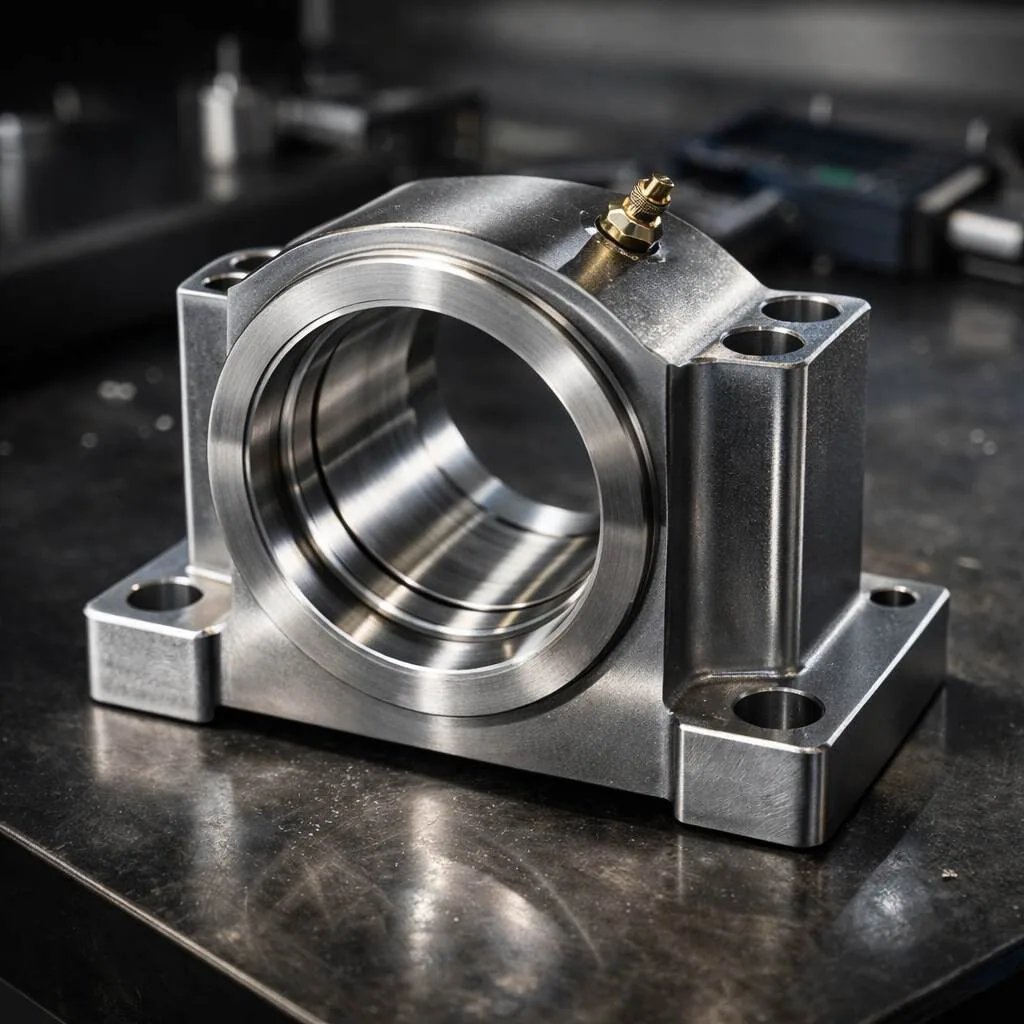
A diameter within limits can still be a poor bearing seat if the bore is tapered, lobed, misaligned or supported by a flexible wall. NTN warns that inadequate shaft or housing accuracy and installation error can misalign the rings and concentrate loading at their edges. Its housing-design guidance calls out fitting dimensions, shape precision, shoulder runout, fillet radius, mounting error and sufficient housing rigidity. [3]
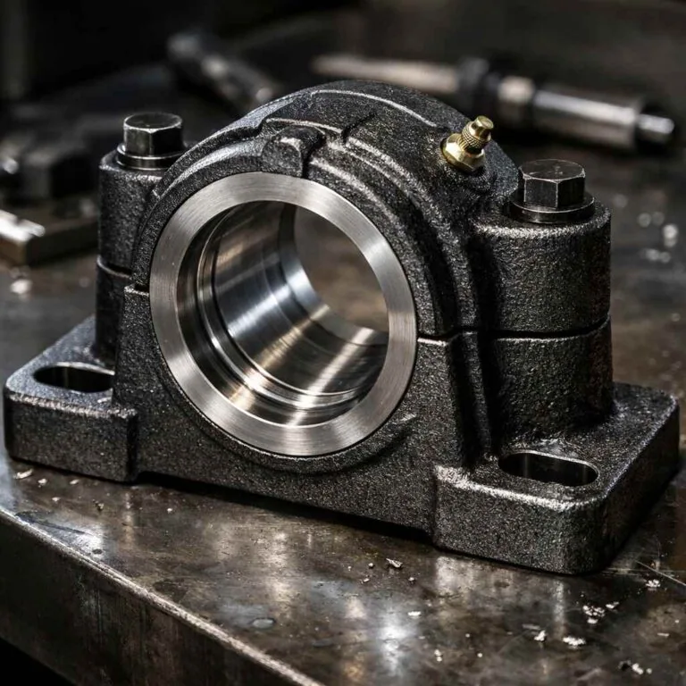
For a split housing, our engineering recommendation is to state the fastener, torque and measurement condition used to accept the assembled bore. For multiple bearing seats, define the datum system and the required relationship between axes and shoulders. For a thin-wall or light-alloy housing, ask the bearing supplier to validate deformation and thermal behaviour rather than copying a fit from a rigid steel housing. These are drawing-review recommendations derived from the cited housing-rigidity and fit-selection factors, not additional catalog tolerances. [1] [3]
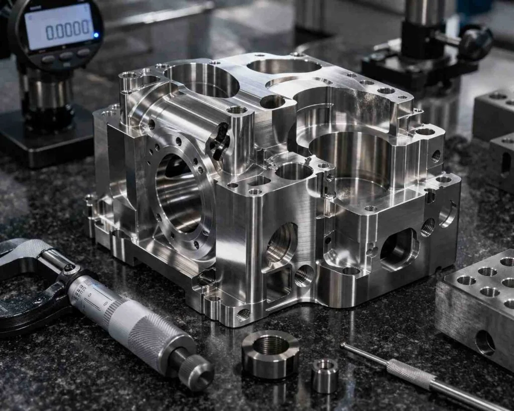
Machining and inspection plan
The inspection plan should verify the functional seat, not only one diameter reading. NTN ties fit performance to dimensional and shape accuracy, surface finish, wall thickness and mounting accuracy. [1] [3]
Recommended process sequence: establish the mounting datums; rough-machine the housing; perform any specified stress-relief or stabilisation step; finish the mounting face and bearing seat in a controlled setup; deburr without rolling an edge into the bore; clean the part; condition it to the agreed inspection temperature; then measure diameter and geometry at the defined sections. The exact sequence should follow the material, geometry and production route on the released drawing.
| Characteristic | Suggested evidence | Reason for inclusion |
|---|---|---|
| Bore size | Diameter at multiple axial and angular locations | Shows whether the full seat remains within its size limits |
| Bore form | Roundness or cylindricity result where specified | Separates size from lobing, taper and barrel shape |
| Seat alignment | Axis relationship to the mounting datum or companion bore | Supports the bearing arrangement rather than an isolated bore |
| Shoulder | Runout or perpendicularity and verified fillet clearance | Supports square seating without fouling the bearing corner |
| Measurement condition | Part temperature, instrument, uncertainty or decision rule as contracted | Makes a close-limit result reproducible |
Bearing housing fit checklist
- Record the exact bearing manufacturer, series, designation, tolerance class and internal-clearance class.
- Draw the radial and axial load directions relative to both rings.
- Identify whether the bearing position locates axially or must float.
- Select the fit from the bearing manufacturer’s current table for the stated material and duty.
- Calculate minimum and maximum resultant clearance or interference from both component limits.
- Check operating temperatures and material expansion with the bearing supplier.
- Specify the bearing seat’s size, form, datum relationships, shoulder, fillet and surface requirements that the design actually needs.
- Define the split-housing clamping state or final assembly condition, if applicable.
- Agree how the bearing will be installed, removed and retained axially.
- State the measurement condition and acceptance evidence in the purchase package.
This checklist is an engineering handoff recommendation. The source principles are NTN’s fit, internal-clearance and housing-design guides; the project owner remains responsible for the final bearing-system analysis. [1] [2] [3]
Frequently asked questions
Is H7 always correct for a bearing housing?
No. NTN lists H7 for particular static outer-ring-load conditions, while indeterminate or rotating outer-ring loads can require transition or tighter classes. The table is also scoped by bearing class, housing material, load and whether axial movement is needed. [1]
What is the difference between a clearance fit and an interference fit?
In a clearance fit, the permitted bore is larger than the permitted mating diameter across the relevant limit combination. In an interference fit, the bearing diameter exceeds the bore across the relevant limits. A transition fit can produce either result. NTN uses loose, transition and tight for these three resultant-fit categories. [5]
What is a bearing interference fit?
A bearing interference fit exists when the permitted bearing diameter is larger than the permitted seat across the limit combination being evaluated. For the outer ring, the result is calculated as bearing OD minus housing bore; it should be reported as a range because both parts have tolerances. NTN calls this a tight resultant fit and cautions that excessive interference can reduce internal clearance and raise operating temperature. [5]
Does a stationary outer ring always need a loose fit?
Not as a universal rule. NTN says a static ring load can be carried with a loose fit, but its selection factors also include load severity, vibration, temperature, material, accuracy and required axial movement. The manufacturer’s application table and review should decide the released fit. [1]
Can an interference fit reduce bearing clearance?
Yes. NTN explains that an interference fit contracts the outer ring or expands the inner ring and thereby reduces internal clearance. The actual reduction depends on the bearing, seat geometry, dimensions and materials. [2]
Should the bore be checked at one depth or several?
Our recommendation is to sample multiple axial and angular locations when the drawing requires the full seat to meet size and form requirements. NTN identifies dimensional accuracy, shape accuracy and misalignment as relevant to bearing performance, so a single reading may not describe taper or lobing. [3]
Is the fit enough to hold the bearing axially?
Not by default. NTN instructs designers to select an axial fixing method able to withstand the axial load, such as a nut, bolts or a retaining ring, and discusses limits for each method. [3]
Preparing a manufacturing handoff
Once the bearing supplier has approved the fit, send the manufacturer the released drawing, bearing designation, material and heat-treatment state, mating dimensions, datum scheme, bore and shoulder requirements, assembly condition, finish requirements and inspection plan. Keeping the functional inputs together reduces the risk that a housing bore is machined to the correct size but the wrong geometric or thermal assumption.
If the design is ready for a manufacturability review, MetalWorksPlus can be included in the supplier discussion. The next step is to share the controlled drawing and fit rationale for a CNC machining review; related housings and other custom components can also be evaluated within the published machine-parts range. These links identify MW+’s published destinations only; this guide does not assert a project result, universal tolerance capability or bearing-design approval.
Technical references
- NTN, Ball and Roller Bearings Technical Explanation 7: Bearing Fits. Fit categories, selection factors, load relationship, tolerance recommendations and numerical resultant fits.
- NTN, Ball and Roller Bearings Technical Explanation 8: Bearing Internal Clearance and Preload. Effects of fit and temperature on operating clearance.
- NTN, Ball and Roller Bearings Technical Explanation 14: Shaft and Housing Design. Axial fixing, housing accuracy, shoulders, misalignment and rigidity.
- ISO 286-2:2010. Limit deviations for commonly used hole and shaft tolerance classes; ISO status checked 10 October 2026.
- NTN Americas, Bearing with Shaft & Housing Fits. Plain-language overview of loose, transition and press fits and operating factors.