







For copper vs brass in a machined contact, compare specified alloys at the same temperature and geometry. Annealed C11000 electrolytic tough pitch copper has higher published bulk conductivity than annealed C36000 free-cutting brass. C36000 is a reference alloy for machinability. Use a resistance budget to decide whether the difference in conductivity matters, then qualify the actual mating interface separately. [1–3]
This guide shows how to choose a contact alloy for a rigid machined component. It uses supplier reference properties and an assumed geometry to compare bulk resistance. The example provides no current rating, temperature rise or contact-life prediction.
Copper vs brass: specify the alloy and material condition
Start the copper vs brass comparison with an alloy designation and stock form. The two examples here are UNS C11000 copper and UNS C36000 brass. Without those designations, the material names leave the alloy and temper open. Ask the material supplier to identify the bar or rod specification, temper, and documentation that will travel with the lot.
For copper vs brass, review the stock condition separately from the condition used in a property table. An annealed reference value is a useful screening input. By comparison, a purchase requirement should describe the actual ordered condition and any minimum or maximum property the design relies on. [1, 2]
In a copper vs brass review, ask procurement to name which properties are contractual. An alloy designation alone does not tell the reviewer which property certificate, sampling method or acceptance limit the assembly design requires. Where the design depends on a specific conductivity, record that requirement explicitly and identify the applicable test method.
For C36000, check the declared composition against the project’s substance restrictions before quoting or approving a substitute. The cited supplier guide describes C36000 as a leaded free-cutting brass. Use current supplier evidence for the material offered to the job. [2]
| Property and condition | C11000 copper | C36000 brass |
|---|---|---|
| Bulk electrical conductivity, annealed at 20 °C (68 °F) | 101% IACS [1] | 26% IACS [2] |
| Volume resistivity at 20 °C used in this guide | ≈1.7071 × 10⁻⁸ Ω·m, derived from 101% IACS [1] | ≈6.6313 × 10⁻⁸ Ω·m, derived from 26% IACS [1, 2] |
| Machining evidence to review | Confirm tool and workholding trial for the specified stock form and temper. | The guide lists an approximate relative machinability index of 100. Confirm actual results on the drawing features. [2] |
IACS means International Annealed Copper Standard. Use 58.0 MS/m for 100% IACS, as represented on the CDA conductivity chart. Then conductivity σ = 58.0 × 10⁶ × (%IACS/100) S/m and resistivity ρ = 1/σ. For copper vs brass, these are screening estimates at the reference temperature; confirm the ordered material condition. [1, 2]
Brass vs copper conductivity: calculate the bulk contribution
A useful brass vs copper conductivity comparison holds the path length and cross-sectional area fixed. Use the shape and temperature that the estimate represents. For a uniform conductor, resistance R in ohms equals resistivity ρ in Ω·m multiplied by length L in metres and divided by cross-sectional area A in square metres. OpenStax explains the uniform-conductor model. [3]
For this copper vs brass example, assume a uniform 20.0 mm long section, a 2.00 mm² cross-section, a 20 °C reference temperature and 2.00 A direct current. Convert 20.0 mm to 0.0200 m and 2.00 mm² to 0.00000200 m². Consequently, the length-to-area ratio is 10,000 m⁻¹. These are teaching inputs for a single straight section.
Using the same geometry, the conductivity-derived C11000 resistivity gives approximately 0.171 mΩ for the section. For C36000, use ρ = 1/(58.0 × 10⁶ × 0.26) Ω·m. As a result, the estimated brass resistance is approximately 0.663 mΩ. Apply V = IR for voltage drop and P = I²R for power dissipated in the uniform section, as derived in OpenStax, University Physics Volume 2, sections 9.4–9.5. [1–3]
| Alloy | Resistance (mΩ) | Voltage drop (mV) | Dissipation (mW) |
|---|---|---|---|
| C11000, reference condition | 0.171 | 0.341 | 0.683 |
| C36000, estimated from the conductivity ratio | 0.663 | 1.326 | 2.653 |
In this brass vs copper conductivity calculation, the estimated brass bulk resistance is approximately 3.88 times the copper value. The absolute difference is about 0.492 mΩ. For copper vs brass selection, compare that difference with the allowable voltage drop allocated to this component. Even so, the ratio alone cannot tell the designer whether either option fits the available budget. [1–3]
The copper vs brass result is sensitive to the length and area of the section being compared. For example, halving the area in the uniform model doubles each calculated resistance. If the drawing permits only a narrow neck on the pin, budget that neck separately before comparing changes to the wider body. [3]
Next, review the drawing for changes in diameter or section. At this point, treat the uniform cylinder as a simplified model. For a stepped component, calculate suitable uniform sections separately and document what the model omits, particularly transition regions and the mating interface. [3]
Translate the material comparison into a machining review
Copper machinability and the features that need a trial
Assess copper machinability on the stock condition and exact features you intend to release. For example, have the supplier review the smallest controlled diameter, cross-hole intersections, the edge at the mating land and how the workpiece will be supported. Ask how it will check those features on first articles.
When comparing copper vs brass, use the C36000 supplier’s machinability reference as a screening input. In practice, the relative rating cannot specify the cycle time, tool life, surface texture or burr limit for a particular drawing. If a quote depends on those outcomes, ask for feature-level evidence. The thyssenkrupp Materials NA guide describes the basis of the C36000 rating. [2]
Before sending out a copper vs brass comparison for quotation, identify which features stay fixed across both options. Hold the drawing revision and inspection criteria constant, then ask the supplier to show any changes to the operation sequence that it expects for each alloy. Review those proposed changes before treating the quotes as comparable.
Likewise, ask how copper machinability will be assessed for the actual bar or rod temper. Then have the supplier report whether the trial meets the specified geometry and surface requirements. Keep the material condition on the inspection record so the production result can be compared with the sample.
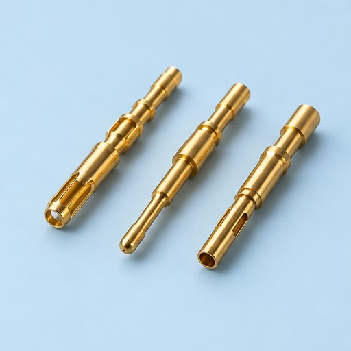
Give the supplier a drawing with the controlled contact land, an agreed reference for its measurement, and the condition in which the diameter is accepted. Review these features with the CNC machining team. For the component family, see machined connector pins.
Release the component and verify the mated interface separately
When deciding how to choose a contact alloy, record the limiting requirement first. It may be the allocated bulk voltage drop, a mechanical feature, the approved substance list or the available form and temper. Then document the evidence needed for the material and the finished component. Separately, set acceptance criteria for the assembled interface.
For copper vs brass, keep incoming material evidence with the part revision and lot identifier. The Copper Development Association alloy guide lists reference physical properties and discusses material conditions. Use its values for initial comparison and confirm property limits for the actual order. [1]
A copper vs brass material change can require review by both the component and assembly owners. On the change record, put the expected bulk resistance beside the actual assembly acceptance requirement. If the finished connector is checked end to end, note which parts of that measurement are outside the scope of the uniform-section calculation.
For electrical contact materials, assign separate responsibility for the machined land, surface system and mated electrical test. Define the measurement points, mating counterpart and conditions with the assembly owner. Consequently, keep the dimensional report and the measured assembly voltage drop as separate records.
For a copper vs brass review, request enough information to reproduce a proposed change. Include the alloy and temper, the finished contact drawing, the assumed temperature, the available resistance budget and any required assembly verification. Share that package with MetalWorksPlus for a manufacturing review of the component.
Key takeaways
- Compare exact alloy and material condition at the same temperature.
- Calculate the bulk contribution using the controlled section and stated assumptions.
- Use the copper vs brass comparison to screen options, then verify manufacturability, substance restrictions and mated performance.
Frequently asked questions
Is C36000 a direct substitute for C11000 in a machined pin?
For copper vs brass substitution, obtain engineering approval before changing the drawing. Compare the specified stock, the bulk-resistance budget, the geometry and the applicable material restrictions. Then confirm how the actual mated interface will be qualified. [1–3]
How should I compare electrical contact materials at the same geometry?
Use resistivity values for the same temperature and relevant material condition. Calculate the uniform section contribution using R = ρL/A. Keep the assembly measurement separate and document its test conditions. [3]
Does the example establish a maximum current for the brass pin?
The assumed 2.00 A current demonstrates the arithmetic for one section of the copper vs brass example. A current limit needs evidence for the actual part and assembly, including the temperature criterion and test conditions. [3]
Can colour identify the alloy used in a finished contact?
For copper vs brass identification, use material certification and lot traceability. Record any specified finish separately and ask the assembly owner to confirm the actual surface system before approving a substitution.