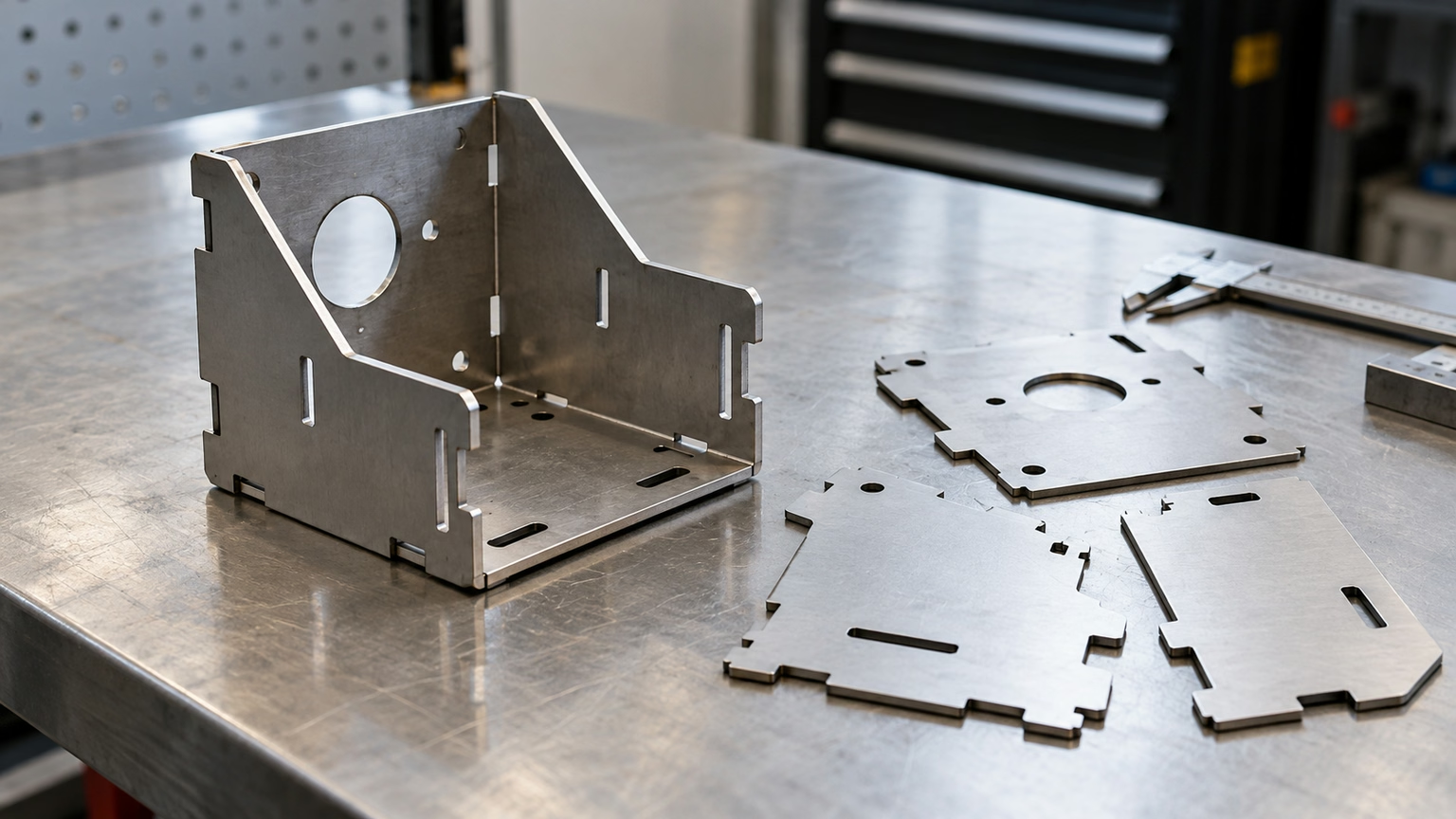








Punch and die clearance is the gap between opposing cutting edges when the punch enters the die. For round, centered tools, the per-side gap is half the difference between the die opening and punch diameters.
Start from the hole when piercing and the retained part outline when blanking. Then check tool size and assembled alignment before releasing the first stamped parts.
Illustrative application guide. The circular tools, dimensions, and acceptance window below are hypothetical. The example shows how to calculate punch clearance and how to turn that calculation into an inspection plan. It describes no customer job, press trial, or measured MW+ capability.
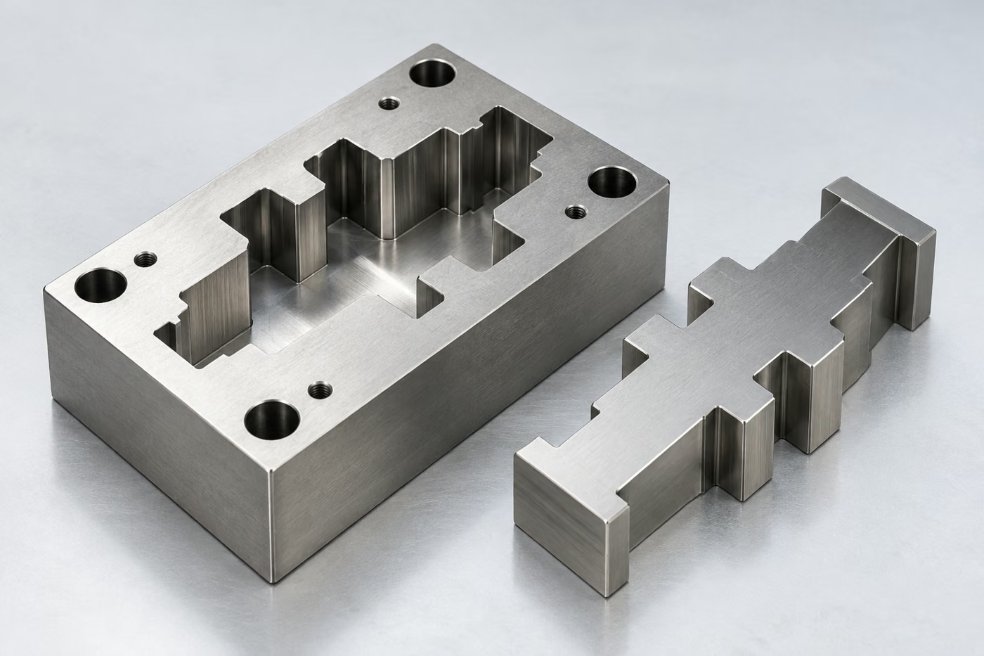
Punch and die clearance: per-side gap and total difference
For a centered circular cutting pair, let D be the die opening diameter and P the punch diameter, both at the cutting land. The total difference is D − P. The per-side gap is (D − P) ÷ 2.
Consequently, a callout of 0.10 mm per side means a 0.20 mm diameter difference.
On a noncircular profile, specify the intended punch die gap normal to the mating edge. For example, opposing parallel walls contribute one gap each to the width difference. At corners and transitions, review the paired profiles in CAD and agree how the corner geometry will be inspected.
A single width reading describes only the measured section. For punch and die clearance at an asymmetric notch, dimension the offset from the controlling edge and identify the inspection section on the drawing.
Also specify where to measure punch and die clearance. A section taken in the relief below the cutting land can give a different opening size.
On the tool drawing, identify the land, the relief, and the datum references used for both cutting profiles. On the part drawing, identify the controlled feature, the burr side where functional, and the acceptance method.
Mate’s die-clearance guide explains how the cut edge and slug can reveal changes in rollover, burnish, and fracture.
However, Mate also points to tool condition and angularity as possible causes. Use the edge appearance to direct the investigation, then measure the tool pair before changing punch and die clearance.
Blanking clearance and piercing: which tool owns the size?
Identify the piece that must meet the drawing
The Mate tooling catalog linked below distinguishes piercing from blanking by the piece being retained. In piercing, the hole remains in the sheet and the slug is discarded. Start from the intended hole size on the punch side and add the total gap to obtain the nominal die opening.
In blanking, the cutout is the retained part. Start from the intended blank outline on the die side and subtract the total gap to obtain the nominal punch size.
For example, with an illustrative 12.000 mm retained feature and 0.200 mm total punch and die clearance, the nominal piercing pair is a 12.000 mm punch and a 12.200 mm die opening.
A blanking pair would start with a 12.000 mm die opening and an 11.800 mm punch. Confirm both layouts against first-off measurements before treating the nominal tool size as the finished-part size.
Review blanking clearance independently when a drawing combines an outer blank with pierced holes. For example, assign the die opening as the initial size reference for the outside and the punch as the reference for each hole. Then give each feature its own size and edge acceptance criteria.
The following values are examples from the Mate Euromac tooling catalog’s clearance table. They apply to the catalog’s listed material categories and thickness bands. The conversions use the assumed sample thicknesses in the first column.
| Catalog material and sample thickness | Piercing, total | Piercing, per side | Blanking, total | Blanking, per side |
|---|---|---|---|---|
| Aluminum, under 2.50 mm. Sample 1.00 mm | 15% | 0.075 mm | 15% | 0.075 mm |
| Mild steel, under 3.00 mm. Sample 1.00 mm | 20% | 0.100 mm | 15% | 0.075 mm |
| Mild steel, 3.00–6.00 mm. Sample 4.00 mm | 25% | 0.500 mm | 20% | 0.400 mm |
For instance, 20% total on 1.00 mm stock is 0.200 mm total and 0.100 mm per side. Treat the table as a starting reference for that tooling system.
Before selecting blanking clearance for a new job, confirm the actual stock grade, thickness range, and edge requirement with the toolmaker. Record whether its proposed percentage is per side or total.
On a shared drawing, label punch and die clearance separately for the outside profile and for pierced features if the accepted gaps differ.
Calculate size variation and assembled clearance
Worked example: 12 mm circular piercing pair
To show how to calculate punch clearance with tolerance, assume a punch of 12.000 ± 0.010 mm and a die opening of 12.200 ± 0.010 mm at the cutting lands.
Assume round profiles in one plane and up to 0.020 mm of assembled center offset. These inputs are selected for the arithmetic and do not specify toolmaking capability.
First, use the smallest die and largest punch to calculate the smallest centered gap: (12.190 − 12.010) ÷ 2 = 0.090 mm.
Next, use the largest die and smallest punch for the largest centered gap: (12.210 − 11.990) ÷ 2 = 0.110 mm. Each is a per-side result. The range is the centered punch and die clearance budget before the tool assembly contributes positional variation.
Then apply the maximum center offset along the line joining the centers.
The close side loses 0.020 mm and the far side gains 0.020 mm. Therefore, the modeled local punch and die clearance across the dimensional and offset extremes spans 0.070–0.130 mm.
| Condition | Die minus punch diameter | Centered gap per side | Close side at 0.020 mm offset | Far side at 0.020 mm offset |
|---|---|---|---|---|
| Small die and large punch | 0.180 | 0.090 | 0.070 | 0.110 |
| Nominal sizes | 0.200 | 0.100 | 0.080 | 0.120 |
| Large die and small punch | 0.220 | 0.110 | 0.090 | 0.130 |
Suppose the hypothetical local acceptance window is 0.080–0.120 mm. The centered size extremes pass.
However, the assembled extremes fail on both sides of the window.
Holding both size tolerances fixed leaves at most 0.010 mm of center offset in this model, before allocating anything to measurement uncertainty, form, tilt, or load effects.
Accordingly, ask which measurements support the assumed alignment and whether the guides, inserts, and retainers share a functional reference. If the actual profiles depart from roundness or the axes tilt, check local punch and die clearance in the relevant cutting planes using measured geometry.
A flat circular model cannot quantify those effects. Also distinguish a radial offset from a diametral position zone.
For example, a single center in a circular position zone of diameter 0.020 mm may lie at most 0.010 mm from its nominal center. Derive relative offset from the relevant features and datums before adding it to a punch and die clearance budget.
Translate the clearance budget into a machining plan
Wire EDM tooling: separate path compensation from cutting clearance
Wire electrical discharge machining (EDM) uses controlled electrical discharges and a wire electrode.
In wire EDM tooling, machine compensation establishes the cut profile. Punch and die clearance is the finished relationship between the two parts. Therefore, issue separate finished profile requirements for the punch and die rather than treating the wire path offset as an assembly gap.
Makino’s wire EDM tutorial explains how cutting conditions and wire deflection can affect straightness and corner accuracy.
For this job, ask the wire EDM tooling supplier how it will verify profile size and straightness at the specified insert thickness. Agree on inspection evidence before assuming that a particular number of finishing passes will suffice.
For example, the routing review can assign blank preparation, reference faces, and mounting features to CNC machining services, with through-cut profiles reviewed separately under electrical discharge machining.
Define the datum handoff on the print so both operations locate the profile from the same functional reference.
Also ask where the wire will enter or exit and how the supplier plans to verify corners and transitions. Identify any cutting-land faces requiring finish, form, or orientation limits.
If the tool sits in a replaceable holder, include the holder interface on the datum review so the size report can be related to assembled punch and die clearance.
Verify the tool pair and the first stamped pieces
Inspect tool components and the assembled pair separately
First, measure both cutting profiles at their drawing-defined planes. Record feature size, location, and any required profile or orientation result from the specified datums.
Then check the assembled relationship using a method suited to the allowed gap and the measurement uncertainty. Retain the measured position relationship with the individual tool reports.
Where a punch and die clearance limit is close to the method’s uncertainty, agree on how to handle borderline results before the trial.
Next, check representative first-off parts against the part drawing. For a pierced hole, agree which portion of the edge or depth defines the accepted diameter.
For a blank, agree how the outside edge and burr will be measured.
If the trial shows different edge conditions around the perimeter, compare the part and slug observations with local punch and die clearance and the recorded tool alignment.
Finally, keep the trial inputs traceable. Record sheet grade and thickness, tool revision, insert pair, press setup reference, and measurement method.
If the team changes the punch, die, or locating interface, repeat the affected checks. That record helps distinguish a changed tool setup from a changed stock condition.
When reporting punch and die clearance, label each value as nominal, derived from actual tool measurements, or measured in assembly.
When requesting a tooling review from MetalWorksPlus, include the part and tool drawings, the retained-feature definition, and the required inspection output. If the job also includes replaceable holders or other machined components, include the mating drawings and shared datum scheme.
Key takeaways
- State punch and die clearance per side or total and identify the cutting land.
- Assign the controlling tool from the retained feature: punch for piercing, die for blanking.
- Check tool sizes, assembled alignment, and the first stamped parts as separate acceptance steps.
Frequently asked questions
Is the punch die gap per side or total?
It can be specified either way. In a centered circular pair, the per-side gap is half the die-minus-punch diameter difference. Write the convention and units on the drawing and quotation.
Why can two tools within size limits still miss the clearance target?
An offset shifts the local punch and die clearance in opposite directions around the pair. In the worked example, acceptable diameters still produce a 0.070 mm minimum gap when the centers are offset by 0.020 mm.
Can I use a catalog percentage for any sheet material?
Use the catalog punch and die clearance value within its stated material, thickness, operation, and tooling context. Confirm the selected value with the toolmaker and check the first stamped pieces against the actual drawing.
Can the EDM compensation value be used as the inspection limit?
Specify and inspect the finished cutting profiles and their assembled relationship. The machine compensation is a machining input. The acceptance limit belongs on the tooling drawing and should refer to the measured geometry.