







Ball screw end machining starts with the selected support arrangement and its approved interface drawing. Define bearing seats, shoulders, threads and coupling features together, then specify how their relationship to the intended shaft reference will be inspected. Do not choose journal tolerances from shaft diameter alone.
Illustrative application guide: This article is a drawing-review exercise, not a completed MetalWorksPlus customer project. Every dimension in the worked examples is hypothetical. The examples demonstrate dimensional arithmetic, not a recommended bearing fit, preload setting, machining capability or validated ball screw assembly. No catalog dimension is transferred to an unspecified support unit.
Contents
Here is how to specify shaft ends: identify the screw, support units and coupling, obtain their approved interface drawings, and assign inspection evidence to each controlled feature.
Ball screw end machining: define the support arrangement
THK’s support-unit catalog distinguishes fixed-side and supported-side units.
In the illustrated families, the fixed side incorporates a preloaded angular bearing arrangement, while the supported side uses a deep-groove ball bearing. [1] This is manufacturer-specific context, not a rule for every ball screw system.
Start the ball screw end machining review by identifying the complete screw and nut designation, support units, coupling and approved assembly drawing.
Next, mark which end is associated with each support, and identify the drive connection.
Then, record the exact document revisions used to define the interfaces.
A familiar housing shape is insufficient to establish interchangeability.
The catalog also provides recommended shaft-end shapes for its support families. [1] Use the selected product’s current drawing to obtain actual seat, shoulder, thread and retention requirements.
Do not copy a dimension from a similarly named unit or assume that fixed-side and supported-side ends are identical.
For a ball screw end machining enquiry, share a marked-up end arrangement and flag the interfaces that still need approval.
Then, separate confirmed interface requirements from open decisions.
A manufacturer can then review a defined component instead of inferring the support system from a bare shaft model.
Ball screw end support and the supplied screw blank
NSK distinguishes its A-Series with machined shaft ends from S-Series products with unmachined, unhardened shaft ends intended for reworking. [2] That distinction belongs to those product descriptions.
It is not evidence that an arbitrary ball screw has soft, machinable ends.
Before ball screw end machining, ask the screw supplier to confirm the blank condition and permitted end modification. Record the supplier’s drawing revision with that confirmation.
Next, keep the approved modification scope with the drawing.
However, if the supplied article is already a finished assembly, obtain instructions applicable to that article before treating it as machining stock.
Therefore, do not infer heat-treatment boundaries from surface appearance.
Build the shaft-end drawing around its interfaces
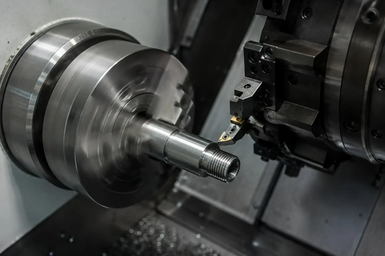
For ball screw end machining, prepare a drawing that makes each interface understandable in section and in its assembly context.
On the section view, distinguish the bearing seats from the locating shoulders, retention features and coupling land.
Next, record which features are final-machined and which arrive in a supplied condition.
Then, ask the responsible designer to resolve any conflict between the screw drawing and the support-unit drawing.
For bearing seats in ball screw end machining, request the approved diameter limits, effective contact length, shoulder requirements and relevant surface condition.
In addition, for the coupling end, identify the mating component and its drawing.
If a keyway is needed, refer its torque and fit review to the separate shaft keyway design review; this article does not qualify a keyed connection.
For ball screw end machining, use the bearing supplier’s actual requirements to establish the seat fit.
For the housing-side interface, see the separate bearing housing fit example.
A housing bore example should not be substituted for a shaft journal specification.
A useful ball screw end machining recommendation is to annotate a reference copy with the function of each dimension: radial seating, axial location, nut engagement, coupling engagement or installation access.
That annotation lets the reviewer see where an interface is missing and which surfaces can keep general tolerances.
Bearing seats: check the hypothetical diameter budget
This ball screw end machining example asks whether an invented pair of diameter intervals guarantees clearance.
Assume a journal diameter of 18.000 ±0.005 mm and an invented bearing-bore interval of 18.000–18.008 mm.
These are teaching inputs only, not a fit class or the dimensions of a selected catalog bearing.
First, define diametral clearance as C = bore diameter − journal diameter.
In this model, a positive calculated value means a diameter gap in this simplified comparison.
Conversely, a negative value means diametral interference.
However, the model omits form, surface texture, temperature, measurement uncertainty and the assembly method.
| Quantity | Lower value (mm) | Upper value (mm) | Meaning |
|---|---|---|---|
| Assumed journal diameter | 17.995 | 18.005 | 18.000 ±0.005 mm |
| Assumed bearing bore | 18.000 | 18.008 | Invented interval, not a catalog specification |
| Calculated clearance extremes | −0.005 | +0.013 | Bore minimum minus journal maximum; bore maximum minus journal minimum |
For example, the lower extreme is 18.000 − 18.005 = −0.005 mm; the upper extreme is 18.008 − 17.995 = +0.013 mm.
Thus the assumed limits permit both interference and clearance.
Therefore, calling the nominal sizes equal does not resolve the assembly outcome.
Use this ball screw end machining calculation to identify whether the approved diameter limits allow clearance, interference or both.
Ask the responsible engineer to select the real bearing journal tolerance using the actual support arrangement and manufacturer requirements.
Next, replace the invented limits with approved ones and repeat the calculation.
However, do not tighten the journal arbitrarily just to make the table appear satisfactory.
In the ball screw end machining calculation, keep the sign convention on the calculation sheet.
For example, if a colleague instead reports interference as journal minus bore, the signs reverse.
Therefore, state whether values are diametral or radial before using them in any downstream model.
In addition, record units consistently so that a micrometre allowance is not mistaken for a millimetre value.
Review the axial stack before discussing preload
The second ball screw end machining example addresses a different issue: can the assumed axial dimensions establish the intended relationship between a bearing-and-spacer stack and a locating distance?
The stack represents an abstract set of locating surfaces.
For this example, assume an axial component width B = 12.00 ±0.01 mm, spacer length S = 2.00 ±0.02 mm, and reference distance A = 14.00 ±0.03 mm.
For this illustration only, define the geometric remainder G = A − (B + S).
Positive G indicates remaining axial space in the model; negative G indicates dimensional overlap.
Neither is a preload value.
| Assumed input or calculated result | Minimum (mm) | Maximum (mm) | Basis |
|---|---|---|---|
| Component width B | 11.99 | 12.01 | Assumed 12.00 ±0.01 |
| Spacer length S | 1.98 | 2.02 | Assumed 2.00 ±0.02 |
| Combined width B + S | 13.97 | 14.03 | Sum of respective limits |
| Reference distance A | 13.97 | 14.03 | Assumed 14.00 ±0.03 |
| Remainder G | −0.06 | +0.06 | A minimum minus stack maximum; A maximum minus stack minimum |
The nominal remainder is zero, but the extreme combinations span −0.06 to +0.06 mm.
The example therefore does not demonstrate a guaranteed zero-gap assembly.
Review the actual locating and clamping arrangement to determine how it accommodates that dimensional variation.
Therefore, do not convert this remainder into bearing preload using an invented stiffness or a universal nut torque.
In particular, the calculation contains only lengths.
Consequently, any preload or clamping analysis requires the actual manufacturer’s assembly procedure and the relevant mechanical model.
THK’s description of preadjusted support-unit bearings is specific to its documented construction. [1]
For a real ball screw end machining stack, draw the contact sequence and identify which surfaces actually locate one another.
Then, include the components present in the released assembly rather than adding every nearby length.
However, if the real arrangement differs from this teaching model, derive its own equation and make the sign convention explicit.
Specify threads, reliefs and coupling access
For ball screw end machining, use the selected retention hardware to define thread designation, usable engagement, permitted runout region and access for assembly.
Next, show where the thread ends relative to the bearing seat and shoulder.
Then, require confirmation that the nut and tool can reach their intended positions without an unapproved interference.
THK’s support-unit catalog illustrates collars, locknuts and retention features as part of its assemblies and shaft-end arrangements. [1] Those drawings are reasons to review the complete interface; they are not authorization to reuse a catalog thread on another screw.
In ball screw end machining, ask for approval of any proposed relief, corner or transition at the journal shoulder.
Next, record the applicable mating-component requirement on the drawing instead of leaving the manufacturer to infer it.
For clarity, this guide intentionally supplies no universal shoulder radius, thread class, groove size or tightening torque.
For the coupling in ball screw end machining, specify the actual mating drawing and required engagement region.
Keep shaft alignment and installation instructions with the assembly documents.
However, a shaft-end diameter and thread callout alone do not define the complete drive connection.
Therefore, where the coupling proposal changes, review its interfaces before retaining the old machining drawing.
Plan inspection and release for the completed shaft end
Shaft alignment and inspection references
For ball screw end machining, identify the intended reference axis and the features controlled relative to it.
Ask the designer to define which geometric requirement applies to the journal, shoulder face and coupling land, and which surfaces establish the inspection setup.
In particular, avoid using the general phrase “keep concentric” as the complete acceptance instruction.
On the ball screw end machining inspection plan, pair each controlled feature with the evidence required to accept it.
For a journal, request diameter results at agreed locations and the method used.
Likewise, for a shoulder or alignment requirement, request the specified geometric result with the reference setup recorded.
Then, agree on uncertainty and acceptance decisions for the actual limits rather than selecting an instrument solely by its display resolution.
Next, separate component inspection from assembled ball screw mounting.
NSK’s bearing mounting guidance distinguishes mounting methods and directs attention to bearing type and fit. [3] A dimensional report should not be presented as evidence that an assembled drive has achieved its functional requirements.
After ball screw end machining, during assembly review, identify the supplier’s installation instructions, relevant mounting surfaces and required functional checks.
Then, record who is responsible for accepting shaft alignment and operation.
In addition, keep any observed condition tied to the actual screw, supports, coupling and drawing revision.
Do not infer service life, critical speed or load capacity from the two dimensional tables.
This release review explains how to specify shaft ends without treating a nominal diameter or a zero nominal stack as an approved assembly requirement.
Key takeaways
- Define ball screw end machining from the actual support arrangement and approved drawings.
- Calculate diameter and axial limits separately, using explicit sign conventions.
- Keep component inspection, assembly alignment and functional validation as distinct acceptance decisions.
Release the machining and assembly package
Before requesting ball screw end machining, bring the screw identification, support-unit drawings, shaft-end drawing, material and supplied condition, coupling details, retention hardware and inspection requirements into one controlled package.
Next, mark unresolved interface questions visibly.
Finally, require proposed substitutions or drawing deviations to be returned for approval.
Discuss the journals, shoulders and threads through MW+’s CNC turning service information.
Place the shaft in the context of custom machined mechanical parts, then use the CNC manufacturing review to clarify the proposed operations and inspection scope.
Send MetalWorksPlus the approved interface package and request feature-specific feasibility confirmation.
The ball screw end machining release decision should state what has been established: an approved drawing, a reviewed manufacturing route, an accepted component or an accepted assembly.
Then, preserve the evidence for each step.
No ball screw end machining calculation or photograph in this guide replaces the applicable manufacturer’s instructions or the engineering approval of the actual system.
Technical references
- THK: Ball Screw Peripherals, Support Units. Manufacturer catalog showing fixed/supported constructions, components and shaft-end arrangements. Use the current selected part drawing for actual requirements.
- NSK: Ball Screws, Products. Manufacturer distinction between machined shaft ends and unmachined, unhardened end products.
- NSK: Bearing Mounting. Manufacturer mounting-method context; not a substitute for the selected ball screw support instructions.
Sources rechecked 14 November 2026. Dimensional tables are original assumed-input calculations. Review questions are engineering recommendations, not measured results, universal specifications or MW+ capability claims.
Frequently asked questions
Can I use one standard end shape for every ball screw?
Select the end shape from the actual screw and support-unit requirements.
THK documents different fixed and supported families and associated recommended end arrangements. [1] Do not assume that another family shares the same interface.
What bearing journal tolerance and ball screw mounting checks are needed?
Obtain the approved limits for the selected bearing/support arrangement. For mounting, verify the actual unit instructions, datum relationships and separate assembly acceptance requirements.
Table 1 is an invented interval exercise, not a fit recommendation or an ISO fit designation.
Does a zero nominal axial gap prove correct preload?
No.
The hypothetical stack has a zero nominal remainder but nonzero extreme remainders.
Moreover, its equation contains lengths only; it calculates neither force nor bearing preload.
Can an existing ball screw always be machined at the ends?
Confirm the particular product’s supplied condition and permitted modification.
NSK’s distinction between finished and unmachined, unhardened ends is product-specific. [2] It should not be generalized to an unidentified screw.