







Compare laser cutting vs plasma cutting against the finished drawing. Screen both routes for material and thickness, then compare evidence for the smallest critical features, edge condition and complete part cost.
This guide shows how to compare cutting quotes and specify what a supplier trial should measure. All dimensions and prices in the worked examples are hypothetical.
Contents
Laser cutting vs plasma cutting: how the processes differ
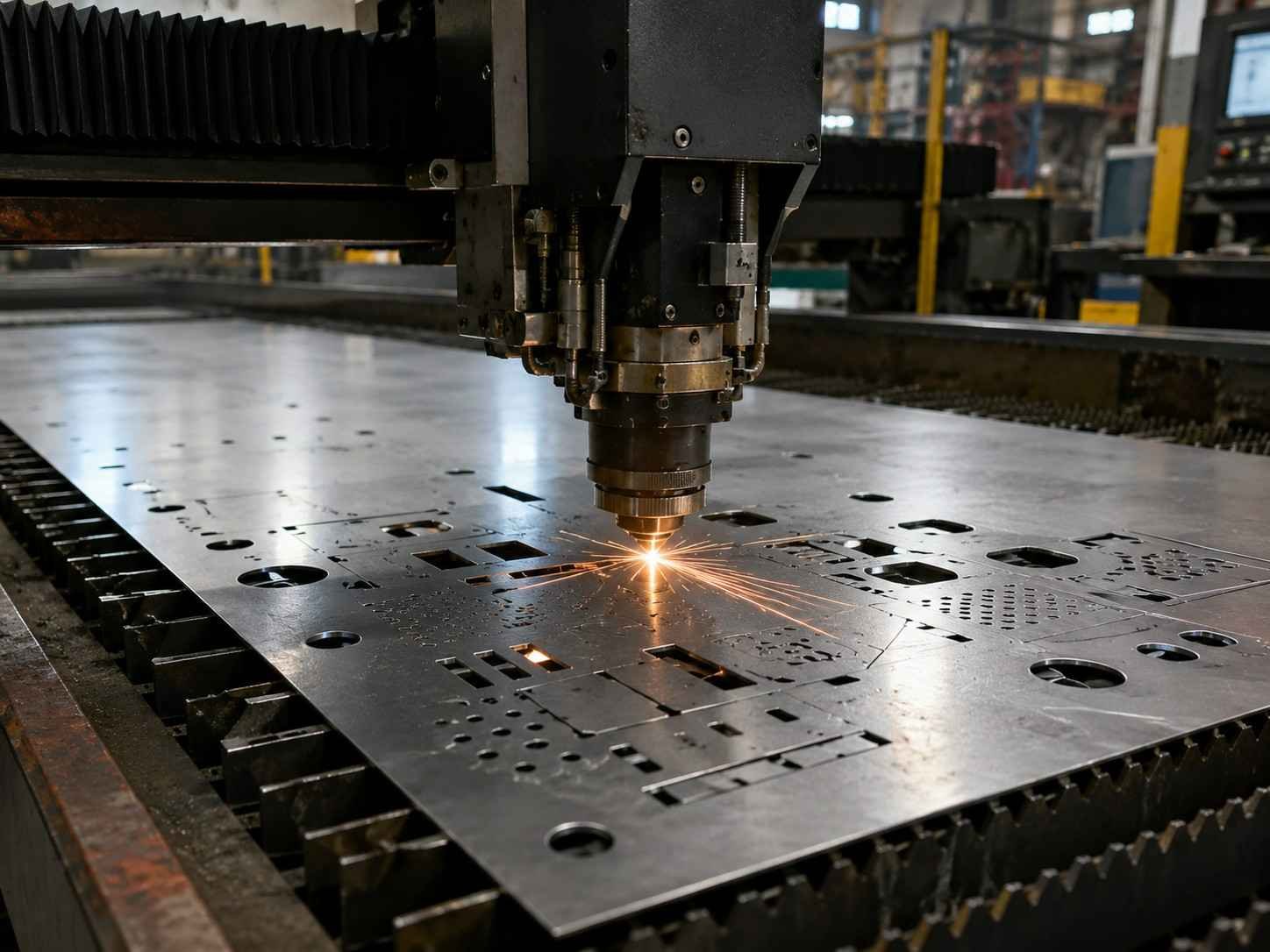
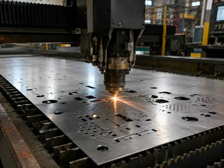
TRUMPF describes laser cutting as a process in which a focused beam heats material until it melts or vaporizes.
Its technical explanation identifies cutting gas and the nozzle as parts of the removal process, and discusses focus position, nozzle diameter and cutting speed as process parameters. TRUMPF’s laser cutting guide
Hypertherm describes plasma arc cutting as transferring energy through a plasma stream to an electrically conductive work material. Gas passes through a nozzle; electrical energy ionizes the gas, and the resulting stream melts and removes material. Hypertherm’s plasma technology guide
Therefore, the mechanism explains why electrical conductivity belongs in a plasma feasibility review.
When screening laser cutting vs plasma cutting, start with material grade, thickness and the proposed machine configuration. Next, ask the suppliers in the laser vs plasma comparison which features need a second operation.
Laser vs plasma: compare the same drawing requirements
When comparing laser cutting vs plasma cutting, use the same drawing revision and define acceptance feature by feature.
For example, a review might include overall profile size, hole position, hole size, edge orientation, flatness and the condition of a surface that will later mate with another part.
Then specify the applicable requirements separately instead of requesting a single statement of sheet metal cutting accuracy.
For example, assume an illustrative bracket has an external width of 80.00 ±0.10 mm. Its acceptable width interval is 79.90–80.10 mm. However, hole location, edge condition and flatness need separate acceptance checks.
What to request from laser vs plasma suppliers
| Reader’s question | Ask the laser-route supplier | Ask the plasma-route supplier | Decision evidence |
|---|---|---|---|
| Is the material suitable? | Confirm grade, condition and proposed laser configuration. | Confirm conductive work material and proposed plasma configuration. | Material specification and route-specific feasibility response. |
| Will the critical profile fit? | Identify controlled dimensions and the finished inspection stage. | Identify the same dimensions and inspection stage. | Results against the same drawing limits, with the measurement method recorded. |
| Are holes and narrow features acceptable? | Review the actual smallest features and proposed finishing operations. | Review those same features and proposed finishing operations. | Representative feature inspection rather than a photograph alone. |
| Is the thickness practical? | Request evidence for the specified material and thickness. | Request evidence for the same material and thickness. | Applicable process data and, where needed, an approved trial. |
| What is included in the price? | State cutting, finishing, inspection and delivery scope. | State an equivalent finished-part scope. | Comparable quotations with assumptions and exclusions visible. |
Use the laser vs plasma checklist with the same drawing revision, quantity and delivery condition. For example, a supplier may quote a hole as cut while another quotes it drilled after profiling.
Measure hole taper and edge condition
In a trial comparing laser cutting vs plasma cutting, assess edge appearance and geometry separately. Hypertherm documents hole taper and lead-in marks as separate issues for specific plasma configurations. Hypertherm’s equipment comparison
Hypothetical hole check: Assume a 6.00 mm plate has a circular hole measuring 12.20 mm at the entry face and 11.90 mm at the exit face.
If the hole is coaxial and the wall is a straight conical surface between those planes, the radial change is (12.20 − 11.90)/2 = 0.15 mm.
Then calculate the wall angle from the hole axis as arctan(0.15/6.00), or approximately 1.43°. Use the result to understand the assumed geometry.
For example, if a separate hypothetical drawing requires a diameter of 12.00–12.30 mm at both faces, the entry value meets that condition and the exit value does not.
However, the two diameters do not establish roundness, location, local marks or the actual wall profile between the faces.
In practice, agree the measurement planes, method and handling of uncertainty before comparing trial parts.
How kerf changes the amount of material removed
First, define cutting kerf as the width of the removed strip measured across the cut path.
Assume a straight path of length L, constant kerf k and constant sheet thickness t. Ignore taper, corner effects, piercing, start and end transients, overlapping cuts and any variation through the thickness.
With those assumptions, the removed strip’s plan area is A = L × k, and its ideal geometric volume is V = L × k × t.
If the cut is symmetric about its centerline, its half-width is k/2. These expressions follow directly from rectangular geometry; they are not empirical process settings.
Cutting kerf in a 1,000 mm worked example
| Assumed kerf k (mm) | Ideal half-width k/2 (mm) | Plan area Lk (mm²) | Ideal volume Lkt (mm³) |
|---|---|---|---|
| 0.20 | 0.10 | 200 | 600 |
| 0.80 | 0.40 | 800 | 2,400 |
| 1.60 | 0.80 | 1,600 | 4,800 |
For example, the first row checks as 1,000 mm × 0.20 mm × 3.0 mm = 600 mm³.
Likewise, increasing the assumed width by a factor of four, from 0.20 to 0.80 mm, increases that model’s volume by the same factor. The calculation shows sensitivity to assumed width.
For production, verify compensation with the proposed machine and control method. The model merely identifies a geometric distance from the assumed centerline to the assumed edge. Actual compensation requires the selected equipment’s programming method and validated cutting data, with the retained material side clearly identified.
When reviewing cutting kerf for laser cutting vs plasma cutting, record the removed width separately from the tolerance on the retained part. The former belongs to process planning. The latter governs inspection.
Thickness and feature feasibility
For laser cutting vs plasma cutting, use maximum thickness only as a screening input. Then ask for evidence that the proposed machine can hold the finished feature requirements at the specified thickness.
Next, mark the critical internal corners, narrow webs, smallest holes and mating edges on the same drawing revision. Then ask which features the proposed route will cut to final condition and which will need another operation. Finally, flag proposed drawing changes for engineering approval.
If a feature is critical, define a representative trial that includes it. Then request its actual acceptance measurement and the conditions needed to interpret the result. For example, attach a photo alongside the measured exit diameter if the supplier reports hole taper.
Compare finished-part quotes and trial evidence
Here is how to compare cutting quotes for laser cutting vs plasma cutting. First, match drawing revision, quantity, material condition, finishing, inspection and delivery.
Then separate one-time preparation charges from recurring part charges. Finally, ask who will accept the finished features and whether the quote includes any secondary operations.
For example, consider two hypothetical quotes in currency units (CU). Either quote could describe a route in a laser cutting vs plasma cutting review. The times and rates are assumed.
- Route A: assumed preparation 30 CU plus 8 minutes at 0.80 CU/minute. Calculated subtotal: 30 + (8 × 0.80) = 36.40 CU.
- Route B: assumed preparation 15 CU plus 15 minutes at 1.20 CU/minute. Calculated subtotal: 15 + (15 × 1.20) = 33.00 CU.
- If route B alone requires an additional assumed finishing charge of 10 CU, its revised total becomes 43.00 CU.
Initially, before the assumed finishing charge, B is 3.40 CU lower. After adding it, A is 6.60 CU lower. For an actual purchase, also include material, inspection and shipping.
For a real comparison of laser cutting vs plasma cutting, replace each assumption with a dated quotation or approved estimate. Then compare per-part prices at the same lot size.
Trial and inspection plan
For a laser cutting vs plasma cutting trial, record the drawing revision, material identification, nominal thickness, proposed route and intended finished condition. Then list the acceptance checks that will decide whether the route is suitable. Finally, give each check an owner, method and required record.
For the assumed 80.00 ±0.10 mm bracket, record the measured width against 79.90–80.10 mm at the agreed inspection stage.
Then record the reading and method together. For example, record the measured width alongside the agreed limits. Evaluate the other features independently.
For laser cutting vs plasma cutting, keep three decisions separate: route feasibility, trial acceptance and agreement on production controls. Then record the evidence supporting each decision.
If an essential feature fails, record the specific result and revise the proposal for laser cutting vs plasma cutting. For example, review a finishing operation or a different route. Keep the original requirement until the responsible design authority approves a change.
Prepare a manufacturing enquiry
For a laser cutting vs plasma cutting enquiry, share the drawing, material, thickness, quantity, critical features and delivery condition. Finally, state whether you need a feasibility review, trial or production quote.
For a project discussion with MetalWorksPlus, use its published laser cutting service information as the starting point.
If a component also requires machined interfaces, identify them when discussing the next manufacturing step through MW+’s CNC machining services.
Finally, place the profile in its component context using the machine parts range, then request confirmation of the actual proposed route and acceptance plan.
Key takeaways
- Compare laser cutting vs plasma cutting using the same drawing, acceptance checks and delivered condition.
- Measure critical hole dimensions at the specified planes and keep kerf separate from part tolerance.
- Include finishing and inspection when comparing quotes.
Frequently asked questions
How should buyers verify sheet metal cutting accuracy?
For laser cutting vs plasma cutting, compare the same material, thickness and drawing revision. Next, measure the retained profile and any critical holes at agreed locations and at the same stage of finishing.
Does thickness alone determine the process?
Thickness is one input in laser cutting vs plasma cutting. In addition, ask whether the proposed route can meet the smallest critical feature and the specified edge condition at that thickness.
Does a narrower kerf guarantee a tighter tolerance?
Kerf describes the width removed during the cut. Part tolerance specifies the acceptable range of the remaining dimension. Check both independently when comparing laser cutting vs plasma cutting.
Can a lower cutting quote cost more after finishing?
Yes. As the hypothetical quotes above show, a secondary operation can reverse the ordering. Therefore, compare totals for parts in the same delivered condition.