








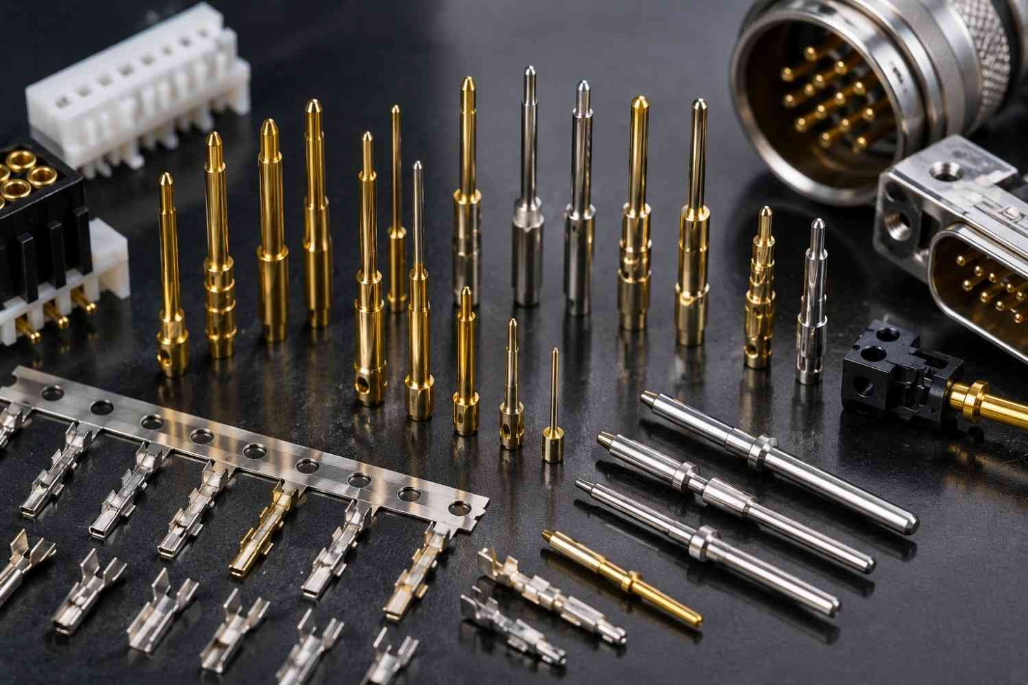
A pogo pin current rating applies to a specified spring-loaded contact and its stated conditions; it cannot be inferred from a machined pin diameter alone. Harwin describes a plunger, body and integrated coil spring, and directs readers to individual connector drawings for design-dependent performance. [1] For a custom component, separate dimensional acceptance from qualification of the complete electrical interface.
This application guide explains how to review spring loaded contact current, resistance measurements and heat generation. All numerical examples below are original hypothetical calculations. They are not measured results, approved operating currents or a completed MetalWorksPlus customer project. No source cited here establishes that MW+ supplies or qualifies a complete spring-loaded assembly.
Contents
Pogo pin current rating belongs to the contact system
Begin with the exact contact part number, drawing revision, counterpart and mounting arrangement. Ask whether the published figure refers to one contact or a connector configuration, and request the test conditions behind it. A catalog heading is a starting point for review, not permission to substitute another plunger, barrel, spring or mating pad.
Harwin’s training material distinguishes miniature spring-loaded contacts from ATE test probes and refers each family to its individual technical drawings. [1] Preserve that distinction when comparing products. A probe used in a test fixture and a contact selected for a docking assembly should be reviewed against their own documents rather than combined into one universal pogo-pin specification.
Our recommended requirements sheet identifies continuous current, any pulse waveform, energized duration, ambient conditions, permitted temperature and the measurement locations used for acceptance. Record the number of simultaneously energized positions and the actual board or wiring arrangement. Where information is missing, mark it as an unresolved design input instead of inserting an assumed catalog condition.
Keep the responsibilities explicit. The mechanical drawing can control a component’s geometry and finish; the assembly validation record should identify what was tested and accepted. Ask who owns the complete contact design and who approves changes. A conforming turned component and a validated electrical connection answer different questions.
Pogo pin contact design: geometry, travel and restraint
Harwin describes a surface-to-surface connection maintained by spring force, with other equipment features holding the system together against that force. [1] For a design review, show both the electrical contact and the mechanical restraint. Do not leave the closure mechanism outside the drawing package when the working position depends on it.
Define the assembled position and tolerance stack
Mark free height, installed gap, intended working position and the manufacturer’s permitted travel on the assembly section. Identify which dimensions belong to the contact supplier and which belong to the surrounding equipment. Ask the designer to check the complete stack at both limits, including any relevant assembly variation, rather than approving the nominal section alone.
For an illustrative stack only, assume free height H = 5.00 ±0.05 mm and assembled gap G = 4.00 ±0.10 mm, measured from the same mounting plane. Compression in this ideal model is x = H − G. The nominal result is 1.00 mm, the minimum is 4.95 − 4.10 = 0.85 mm, and the maximum is 5.05 − 3.90 = 1.15 mm.
These assumed dimensions establish no acceptable travel or spring force. Compare the calculated interval with the actual selected contact drawing and obtain the assembly designer’s disposition. If the applicable working range has not been supplied, the review remains open. Do not infer current capacity from the fact that the nominal position looks plausible.
Control the part without inventing a complete assembly specification
For a machined plunger or body, identify the controlled lands, datum relationships, surface requirements and permitted edge treatments on the released drawing. Ask the contact designer which features affect the intended fit and movement. Avoid adding a generic tight tolerance to every diameter without establishing its function and inspection method.
Specify material and finish through approved drawing requirements. Keep coating identification and verification separate from appearance. A photograph cannot determine the actual alloy, deposited layer thickness or electrical resistance. Review any proposed material or finish substitution with the system owner and define the validation needed before acceptance.
Contact resistance and heat: a checked DC example
For an ideal resistive path under steady DC, voltage drop is V = IR and dissipated power is P = I²R. OpenStax derives these relationships from Ohm’s law and electrical power. [2] Define the endpoints of R before calculating: a number for one interface should not silently become a number for the entire connector circuit.
Assumed inputs: Compare two fixed path resistances, 20 mΩ and 40 mΩ, at currents of 1 A, 2 A and 3 A. These are deliberately assumed values, not contact specifications, measured resistances or recommended test currents. Each table entry is a calculation for a single defined path.
| Assumed current, A | Voltage at 20 mΩ, mV | Power at 20 mΩ, W | Voltage at 40 mΩ, mV | Power at 40 mΩ, W |
|---|---|---|---|---|
| 1 | 20 | 0.020 | 40 | 0.040 |
| 2 | 40 | 0.080 | 80 | 0.160 |
| 3 | 60 | 0.180 | 120 | 0.360 |
Check the middle row by converting 20 mΩ to 0.020 Ω: V = 2 × 0.020 = 0.040 V, or 40 mV; P = 2² × 0.020 = 0.080 W. At the same assumed resistance, increasing current from 1 A to 3 A multiplies calculated power by nine. That ratio follows from the square in the equation, not from a product test.
The table answers how much electrical power the assumed resistance dissipates. It does not answer how hot the contact becomes. No heat-transfer boundary conditions, thermal model or temperature-dependent resistance are supplied here. Do not attach an invented temperature rise to these results or treat the larger value as automatically unacceptable without the actual acceptance criterion.
Use the calculation to formulate a useful validation question: what resistance definition, current condition and temperature evidence support the proposed design? Record the actual answer and its limits. Keep initial resistance, resistance after the required conditioning sequence and the applicable acceptance limits distinct in the review package.
Parallel contacts: calculate sharing before assigning capacity
Two contacts do not receive equal current merely because a drawing labels them identically. In an ideal parallel-resistor model they share the same voltage. Applying V = IR to each branch gives I1/I2 = R2/R1. [2] The following illustration holds total current at 3 A and treats all branch resistances as fixed assumptions.
| Assumed R1 / R2, mΩ | Calculated I1 / I2, A | Common voltage, mV | Calculated P1 / P2, W |
|---|---|---|---|
| 20 / 20 | 1.50 / 1.50 | 30 | 0.045 / 0.045 |
| 20 / 40 | 2.00 / 1.00 | 40 | 0.080 / 0.040 |
| 20 / 60 | 2.25 / 0.75 | 45 | 0.10125 / 0.03375 |
For the second row, equivalent resistance is (0.020 × 0.040)/(0.020 + 0.040) = 0.013333 Ω. Multiplying by 3 A gives 0.040 V; dividing that voltage by each branch resistance gives 2 A and 1 A. Their sum returns the assumed total. The lower-resistance branch carries two-thirds of the current in this model.
Real validation requires the actual branch paths and operating arrangement. Our recommendation is to identify the shared supply and return paths, sense locations, simultaneously loaded contacts and allowed fault states. If the requirement includes continued operation after one branch opens, analyze that specified condition separately. Do not silently turn a two-contact example into a redundancy or current-doubling claim.
Measure the defined current path and temperature
Use separate force and sense connections for low resistance
Keysight describes four-wire measurement using one pair of terminals to source current and another pair to sense voltage at the device. Keithley explains how lead resistance affects two-wire readings and why sense leads should connect at the intended measurement points. [3] [4] Draw the measurement endpoints directly on the test setup.
In a review proposal, identify whether the reported resistance includes the mating surface, internal contact path, solder termination, board trace or fixture. Mark what lies outside the sense points. Retain the test current, instrument configuration, connection method, contact working position and relevant environmental conditions with the result. A bare milliohm value is difficult to compare when its measurement boundary is unknown.
Four-wire measurement addresses lead-related error; it does not establish that a component satisfies every electrical or mechanical requirement. Ask the validation owner to choose the applicable method, uncertainty treatment and acceptance rule. Do not substitute a high-current heating test for a specified low-level resistance test or assume that the two procedures have identical purposes.
Keep thermal observations tied to the tested arrangement
For a thermal trial, propose a record of ambient temperature, current waveform, energized positions, mounting configuration, enclosure state and temperature-sensor locations. Agree the observation period and stabilization criterion before running the test. Report the actual procedure and any deviations instead of presenting an unexplained temperature photograph as a rating.
As a numerical reporting illustration only, an assumed sensor reading of 52°C at an assumed local ambient of 27°C gives a temperature difference of 25°C. This subtraction is not test evidence and establishes no acceptance limit. It also does not identify the hottest internal location. Require the responsible engineer to define which locations and conditions must be assessed.
Release a component drawing and validation brief
Use the following release checklist as an engineering recommendation, adapted to the actual application and governing requirements:
- Identity: Contact and counterpart part numbers, revisions and approved configuration.
- Mechanical position: Installed gap, stack limits, restraint and permitted working range.
- Electrical duty: Continuous or pulsed current, return path and simultaneously loaded positions.
- Acceptance: Defined resistance endpoints, thermal criteria and required conditioning sequence.
- Component drawing: Material, finish, controlled features, inspection method and traceable revision.
- Validation record: Tested assembly, instruments, conditions, actual results and unresolved limitations.
- Change review: Who approves substitutions and determines whether repeat validation is required.
For a component enquiry, discuss the drawing within MW+’s machined contact-pin range. At the manufacturing stage, use the CNC machining review to clarify the requested component features and inspection records. Send MetalWorksPlus the approved drawing and interface requirements; confirm assembly and electrical-validation responsibilities separately.
The related connector-pin specification guide covers the broader component enquiry. This article concentrates on current-rating evidence, loss calculations and validation boundaries. It does not select an RF geometry, prescribe a plating life or establish complete connector qualification.
Frequently asked questions
How to evaluate pogo pin current rating from a drawing?
Diameter alone does not define the complete contact or its acceptance conditions. Start with the selected assembly drawing and applicable manufacturer data, then review the actual configuration. Harwin explicitly treats performance as design dependent. [1]
Does low contact resistance prove an acceptable temperature rise?
Resistance and current allow a resistive-power calculation under the stated model. [2] Temperature acceptance still needs the actual thermal conditions and validation evidence. Table 1 supplies no temperature prediction.
Can I double the current rating by adding a second contact?
Do not assume equal sharing or a doubled rating. Table 2 demonstrates unequal sharing for unequal assumed branch resistances. Validate the complete arrangement against the actual requirements rather than using contact count as the acceptance rule.
What should a contact resistance report identify?
Our recommended record includes sense points, test current, working position, setup and acceptance criterion. Four-wire guidance supports separating source and sense connections at the defined device boundary. [3] [4]
Does this guide confirm MW+ supplies complete pogo-pin assemblies?
No. It is an illustrative application guide for component and validation review. Confirm the requested component scope, available manufacturing route, assembly responsibility and electrical testing separately before an order is released.
Technical references
- Harwin: Spring Loaded Contacts, CP007/30072025. Plunger/body/coil spring, mating restraint, design-dependent ratings and reference to individual drawings; no vendor rating transferred.
- OpenStax University Physics Volume 2, 9.5. V=IR and resistor dissipation P=I²R; idealized steady DC examples.
- Keysight: Four-Wire Resistance Measurement. Separate current force and voltage sense connections for low resistance measurement.
- Keithley/Tektronix: Two-Wire vs Four-Wire Resistance Measurements. Lead resistance errors and sense lead placement at measured device.
Sources reviewed on 28 October 2026. All example dimensions, currents, resistances and temperatures are explicitly assumed. Calculations and review questions do not represent MW+ production, test data or a qualified customer assembly.