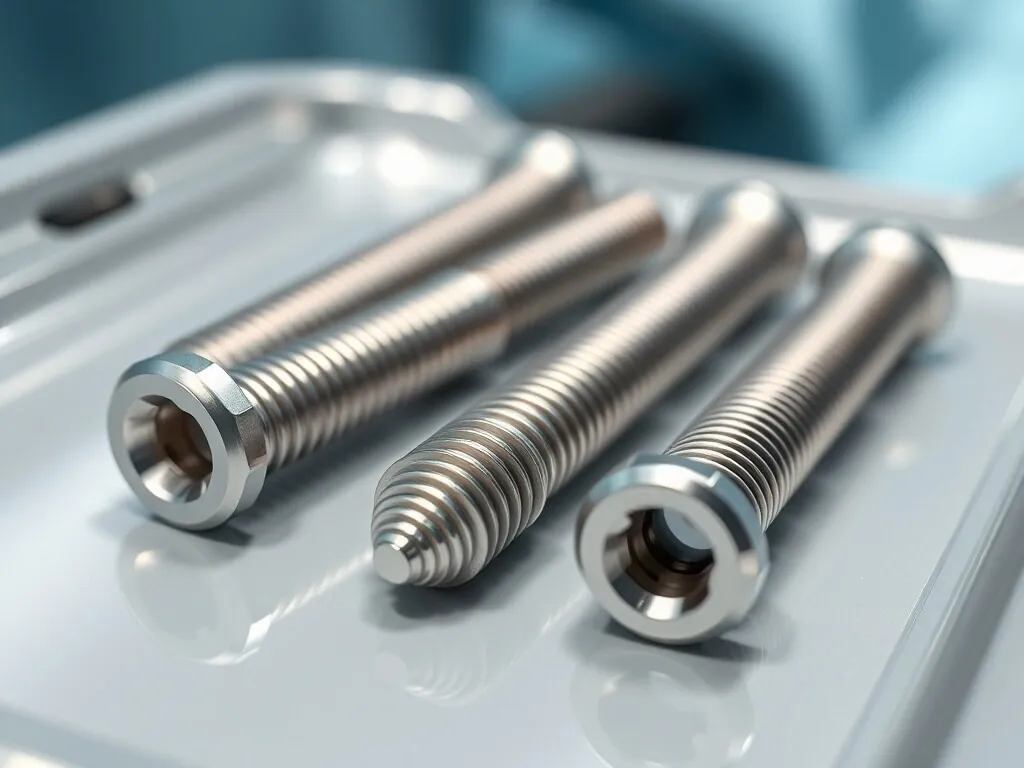
Bone screw machining is one of the least forgiving jobs a Swiss-type lathe can be given. This case study follows a programme of Swiss-turned titanium bone screws for a Class III orthopaedic device, built for a UK design engineer to ±0.001mm on the critical features and shipped with full device history records. It covers the route, the thread whirling step, the inspection plan and the few decisions that decide whether a titanium bone screw passes or fails.
Project at a glance
- Industry
- Orthopaedic implants, Class III device
- Client
- Design engineer, United Kingdom
- Part
- Titanium bone screws
- Process
- Swiss-type CNC turning
- Tolerance
- ±0.001mm on critical features
- Quality system
- ISO 13485, lot traceability
- Records
- Full device history records
- Result
- Delivered to specification
- ±0.001mmon the critical features of each screw
- Class IIIimplant programme, the highest device risk class
- Full DHRdevice history records with every lot
- To specdelivered as drawn, confirmed by the client
“We needed Swiss-turned titanium bone screws at ±0.001mm tolerance for a Class III device. MW+ delivered to spec with full device history records. Exceptional work.”
Design Engineer, Orthopaedic implants, United Kingdom
Why is bone screw machining so demanding?
A bone screw looks simple: a head, a drive recess, a shank and a thread. The difficulty is that every one of those features does a clinical job, and the part is long, slender and made from an alloy that punishes heat and tool wear. Three things make titanium bone screws harder than a general turned part.
First, the geometry. Cortical and cancellous screws use deep, asymmetric buttress threads with a wide pitch, often running most of the screw length. The thread is what holds bone, so its root radius, flank angles and surface condition matter to the surgeon, not just to the drawing. Many designs also add self-tapping cutting flutes at the tip and a central cannulation for a guide wire.
Second, the slenderness. A screw with a length-to-diameter ratio of 10:1 or more deflects under a single-point threading tool. Deflection shows up as a tapered thread, a wandering pitch diameter and chatter marks on the flanks. On an implant, any of those is a reject.
Third, the material. Ti-6Al-4V ELI conducts heat poorly, so the heat of cutting stays at the tool edge. It is chemically reactive with carbide at high temperature and springs back from the tool. That combination wears edges quickly, and a worn edge leaves burrs, which an implant thread cannot carry.
What the client asked for
The brief came from a design engineer at a UK orthopaedic implant company. The device was Class III, the highest risk class under both the EU Medical Device Regulation 2017/745 and the UK’s own device rules. The screws had to be Swiss-turned, held to ±0.001mm on the features the drawing marked critical, and supplied with full device history records so every screw could be traced back to its bar, its machine and its inspection data.
Client names, part numbers and drawing details are not published. The requirements below are the ones that shaped the route.
| Requirement | Why it matters on a bone screw | How it was met |
|---|---|---|
| Implant-grade titanium with mill certificates | Chemistry and microstructure are part of the device’s regulatory file | Bar bought to the client’s material specification, heat number carried on every traveller |
| ±0.001mm on critical features | Fit to the plate, driver and instrument set | Swiss-type turning, in-process gauging, final measurement at 20 °C |
| Burr-free thread and recess | Burrs can detach in the body or damage the driver | Thread whirling, controlled deburr, 100% visual under magnification |
| Consistent thread form along the length | Pull-out strength and insertion torque depend on it | Guide-bushing support at the cut, form checked on an optical system |
| Device history records | Every lot must be traceable and reconstructable | Lot records linking heat, machine, programme revision, operator and inspection data |
Choosing the material route: Ti-6Al-4V ELI or CP titanium?
Most titanium bone screws are made from one of two families. The client’s specification governs the choice, but the machining route changes with it, so it is worth understanding what each implies.
Ti-6Al-4V ELI is specified under ASTM F136 and ISO 5832-3. “ELI” means extra-low interstitials: tighter limits on oxygen and iron that improve fracture toughness. It is stronger than commercially pure titanium, which is why it dominates load-bearing screws.
Commercially pure titanium (Grade 4 is the usual choice for implants) is softer and more ductile. It is gummier to cut, so it builds up on the tool edge and burrs more readily, even though its forces are lower.
| Property (typical, annealed bar) | Ti-6Al-4V ELI (ASTM F136) | CP titanium Grade 4 |
|---|---|---|
| Ultimate tensile strength, minimum | 860 MPa | 550 MPa |
| Yield strength, minimum | 795 MPa | 483 MPa |
| Thermal conductivity | about 6.7 W/m·K | about 17 W/m·K |
| Coefficient of thermal expansion | about 8.6 µm/m·K | about 8.6 µm/m·K |
| Machining behaviour | Heat concentrates at the edge, strong spring-back | Gummy, prone to built-up edge and burrs |
Either way, the material certificate is not paperwork to file and forget. On an implant programme it is the first link in the traceability chain, so the heat number is recorded before the bar is loaded and stays with the lot to the end.
How we machine titanium bone screws on a Swiss-type lathe
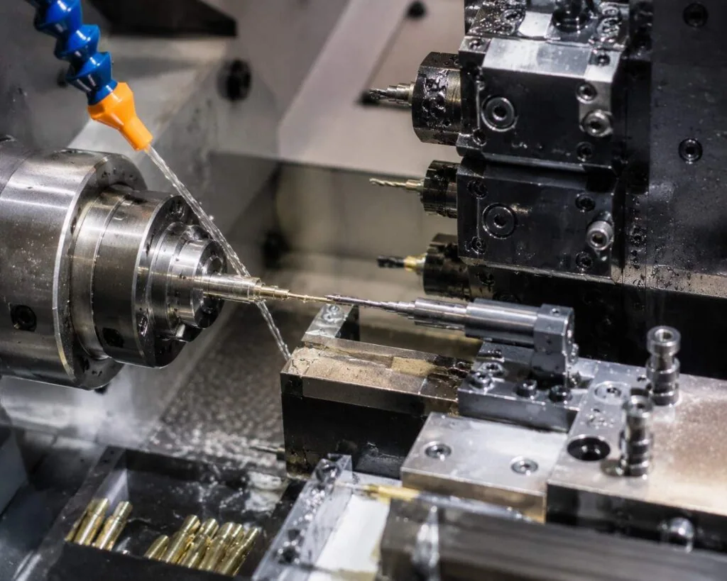
The titanium bone screws were produced on a sliding-headstock Swiss-type lathe. The bar feeds through a guide bushing, and the tool always cuts within a few millimetres of that support. That is the whole point of Swiss machining for long, thin parts: the unsupported length at the cut stays short, however long the finished screw is.
The sequence below is the standard route for this part family. The exact cycle depends on the drawing.
| Step | Operation | What it controls |
|---|---|---|
| 1 | Bar check and loading, heat number logged | Material traceability from the first cut |
| 2 | Face, turn tip and self-tapping flute geometry | Tip form and flute position relative to the thread start |
| 3 | Thread whirling of the shank thread | Full thread form in one pass, no deflection taper |
| 4 | Turn shank and underhead diameters | The ±0.001mm critical diameters |
| 5 | Cannulation drilling where specified | Straightness and concentricity of the guide-wire bore |
| 6 | Head turning and spherical underside | Seating geometry against the plate |
| 7 | Drive recess by rotary broaching on the sub-spindle | Recess form, depth and burr control |
| 8 | Part-off onto the sub-spindle, back-working, eject | Head face finish without re-clamping |
Why thread whirling instead of single-point threading
Thread whirling is the step that makes long titanium bone screws practical. A ring of cutting inserts surrounds the bar and spins at high speed, while the bar itself turns slowly. The whirling head is tilted to the thread’s helix angle, and each insert takes a short, interrupted cut as the ring sweeps around.
Three things follow from that geometry. The thread is cut in a single pass, rather than the 10 to 20 infeed passes a single-point tool needs on a deep buttress form. The cutting force is spread around the bar, so a slender screw is not pushed sideways. And each insert is in the cut only briefly, so heat has time to leave the edge. On titanium, that last point is why thread whirling keeps tool wear and burrs under control.
Drive recesses and burrs
Hex and hexalobular recesses are cut by rotary broaching, where a wobbling broach punches the form into a pre-drilled hole. It is fast and accurate, but it pushes material to the bottom and the rim of the recess. Recess burrs are checked on every lot, because a burr there can shed on the driver during surgery.
Holding ±0.001mm: what actually matters
A tolerance of ±0.001mm gives a total band of 2 µm. At that scale, the machine is rarely the limiting factor. The measurement system, the temperature of the part and the condition of the tool edge decide whether the number is real. Our general-purpose tolerance ladder is ±0.01mm to ISO 2768-m, ±0.005mm for precision work and ±0.001mm for selected features, and this bone screw machining programme sat at the tight end on purpose.
Worked example: where temperature hurts and where it doesn’t
Titanium’s coefficient of thermal expansion is about 8.6 µm per metre per kelvin. Take one of the titanium bone screws in this family, with a critical shank diameter of Ø4.000mm and an overall length of 40mm, measured 5 °C above the 20 °C reference temperature set by ISO 1.
- Diameter growth: 4mm × 8.6 µm/m·K × 5 K = 0.17 µm. That is under a tenth of the 2 µm band.
- Length growth: 40mm × 8.6 µm/m·K × 5 K = 1.72 µm. That is almost the entire band.
The lesson is simple and often missed. On small diameters, temperature is a minor error. On lengths and axial positions, it can consume the whole tolerance. That is why critical measurements were taken on parts soaked to 20 °C, and why the drawing’s datum scheme was agreed before the first chip.
Measurement uncertainty has to be a fraction of the band
A common rule is that measurement uncertainty should be no more than a quarter of the tolerance band. For a 2 µm band, that means an expanded uncertainty of about ±0.25 µm. A hand micrometer cannot do that. Critical diameters were measured on calibrated systems in a temperature-controlled room, and conformity was judged using the decision rules in ISO 14253-1, so a part measured right on the limit is not passed on luck.
The inspection plan for bone screw machining
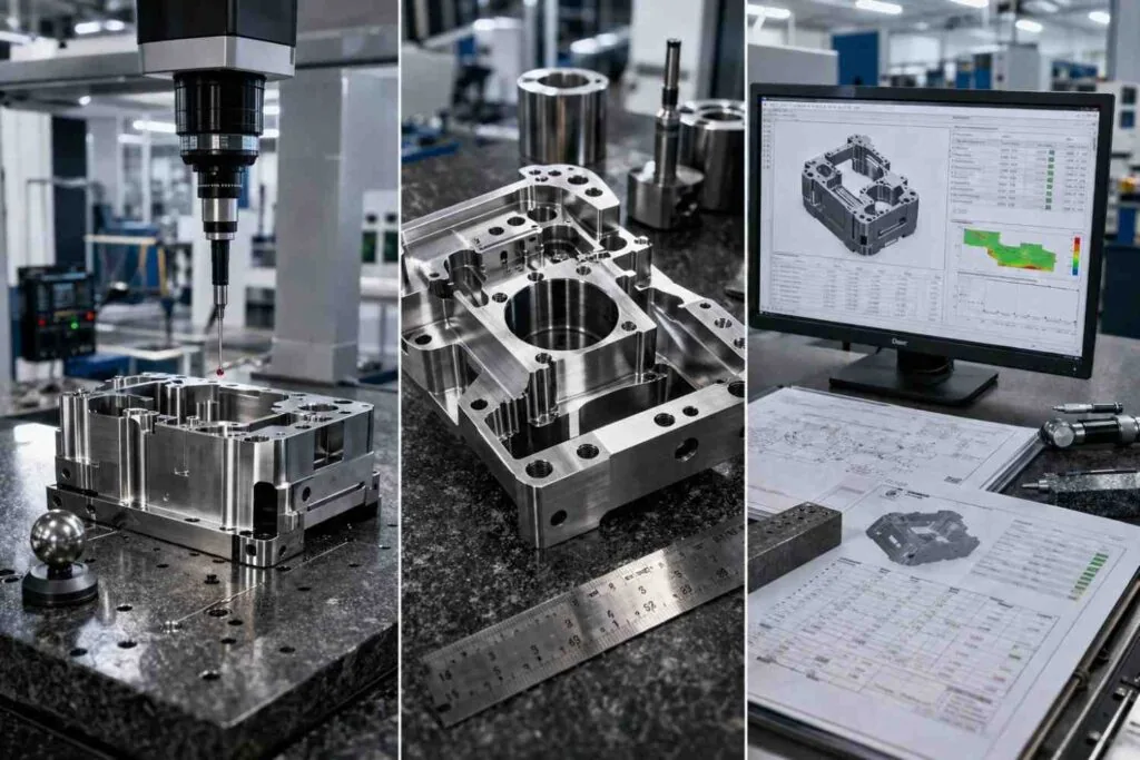
Inspection on an implant screw has two jobs. It has to prove every lot conforms, and it has to leave a record an auditor can read years later. The plan below ran under our ISO 13485 system and the same quality assurance procedures used across the plant.
| Stage | Check | Method | Frequency |
|---|---|---|---|
| First article | Every dimension on the drawing | CMM, optical shaft system, thread gauges | Each new lot and after any programme change |
| In process | Critical diameters | In-process gauging with tool offset adjustment | At a set interval through the run |
| In process | Thread form and pitch | Optical profile comparison | Sampled per lot |
| Final | Critical dimensions at 20 °C | Calibrated instruments, conformity per ISO 14253-1 | Per the agreed sampling plan |
| Final | Burrs, recess form, surface defects | Visual under magnification | 100% |
| Release | Records complete and reviewed | Lot record review before shipment | Every lot |
Device history records: what full traceability looks like
The client asked for full device history records, and on a Class III implant that phrase has a precise meaning. Every screw in a lot must be traceable to the heat of titanium it was cut from, the machine and programme revision that made it, the people who ran and inspected it, and every measurement taken.
In ISO 13485:2016 terms, this is the production record of clause 7.5.1 and the traceability required by clause 7.5.9, with clause 7.5.9.2 adding specific requirements for implantable devices. In the United States, the FDA’s Quality Management System Regulation now incorporates ISO 13485 by reference, so the same records serve both markets.
| Record | What it proves |
|---|---|
| Mill certificate and heat number | The material met its specification |
| Traveller with machine, programme revision and dates | The validated process was the one actually run |
| First article and in-process results | The process was capable at the start and stayed in control |
| Final inspection report | Every released screw conformed |
| Nonconformance records, if any | Anything that went wrong was contained and dispositioned |
| Certificate of conformance | The lot as a whole was released against the drawing |
Our own general approach to traceability in CNC machining is set out in a separate guide. For implants, the difference is depth: nothing in the chain is optional.
The result
This bone screw machining programme was delivered to specification, and the client confirmed it in the words quoted at the top of this page. Every lot shipped with its device history records complete. The claims on this page are limited to what the client stated: Swiss-turned titanium, ±0.001mm, a Class III device, delivered to spec with full records.
About this case study. The client quote is published on our homepage as given. Client name, part numbers and drawing details are not published. The process route and inspection plan describe how MW+ runs this part family.
What other implant programmes can learn from this one
A few points apply to almost every bone screw machining job we are asked to quote.
- Put the tolerance where the function is. ±0.001mm on every feature multiplies inspection time without improving the device. Mark the two or three diameters that mate with the plate or instrument, and leave the rest at a precision band.
- Specify the thread by standard or by full profile. If the thread follows ISO 5835, say so. If it is proprietary, supply the full profile with root radius, because that is where fatigue starts.
- Agree the datum scheme early. On a long screw, the datum decides whether a 2 µm band is measurable at all.
- State the test standard. If the device file relies on ASTM F543 torsion, insertion or pull-out testing, the supplier needs to know which lots are sampled for it.
- Include finishing in the traceability. Anodising, cleaning and packaging steps must write to the same lot record as machining.
When Swiss turning with thread whirling is the wrong choice
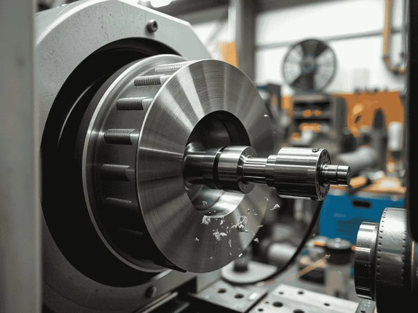
This route suits long, slender titanium bone screws in production quantities. It is not the best answer for every screw.
- Short, large-diameter screws. Below a length-to-diameter ratio of about 3:1, a conventional CNC lathe is stiff enough and usually cheaper. Our CNC turning services cover that case.
- A handful of prototypes. Whirling setup takes time. For one to five pieces of a design that will change, single-point threading on a lathe can be faster overall.
- Designs where thread rolling is validated. Some fixation screws use rolled threads for the cold-worked root. If your device file is built on rolled threads, changing to whirled threads is a design change, not a supplier choice.
- Polymer screws. PEEK and other polymer implants need a different tooling and cleaning approach. See our PEEK medical parts case study.
Frequently asked questions
Can you supply titanium bone screws in Ti-6Al-4V ELI to ASTM F136?
Yes. We buy implant-grade bar to the specification on your drawing, typically ASTM F136 or ISO 5832-3 for Ti-6Al-4V ELI, and ship the mill certificate with the lot. The heat number is recorded before machining starts and carried through to the certificate of conformance.
Do you whirl threads or cut them with a single-point tool?
For long bone screws in production quantities we use thread whirling on Swiss-type lathes, because it cuts the full form in one pass without pushing the bar sideways. For short screws or early prototypes, single-point threading can be the better choice, and we will say so in the quote.
What tolerance can you hold on a bone screw?
We hold ±0.001mm on selected critical diameters, measured at 20 °C with instruments whose uncertainty is a fraction of the band. Thread form is verified by optical profile and thread gauges against the drawing’s thread tolerance, which is usually a different specification from the diameters.
Can you machine cannulated bone screws?
Yes. The cannulation is drilled on the Swiss-type lathe in the same cycle, so it stays concentric with the outside diameter. Long cannulations in small screws need a deep-hole drilling strategy, and we review the length-to-bore ratio at the DFM stage.
Do you provide device history records and lot traceability?
Yes. Every implant lot runs with a lot record that links material heat, machine, programme revision, operators and inspection results. The record is reviewed before release and copies ship with the parts, alongside the certificate of conformance, CMM report and material certificates.
Is MW+ certified to ISO 13485?
Yes. Medical work runs under our ISO 13485 system, alongside ISO 9001:2015, AS9100D and IATF 16949 for other sectors. Certificates are available on request with the quote.
Can you anodise titanium bone screws for colour coding?
Yes. Colour anodising of titanium is controlled as part of the same lot record, so the finish is traceable in the same way as the machining. Tell us the colour code and specification at quote stage, because anodising adds a small amount to the lead time.
What do you need to quote bone screw machining?
A STEP file, a dimensioned drawing with datums and critical features marked, the material specification, annual and first-lot quantities, and any test or documentation requirements. With that, an engineer returns a quote and DFM feedback within 24 hours.
Planning a similar implant programme?
MW+ is a precision CNC machining company in Shenzhen, running Swiss-type turning, 5-axis milling and inspection under ISO 13485 in one 15,000 m² facility. If you are sourcing titanium bone screws, pins or other small implant components, our guide to medical device CNC machining explains what an ISO 13485 supplier should hand you, and our Swiss screw machining guide covers the process in more depth.
Send the drawing for your bone screw machining project and your documentation requirements. You will get a price, a lead time and written DFM feedback within 24 hours, with a straight answer on which features genuinely need ±0.001mm.