Shaft keyway design requires more than selecting a key width: define the torque, key engagement, shaft and hub geometry, fit, machining access and acceptance evidence together. A parallel keyed joint transfers torque through the key and mating keyways. Geometry selection and load verification are separate tasks; a standard-sized key is not, by itself, a torque rating. [1] [3]
Application-guide disclosure: the following shaft-and-hub example is hypothetical. Loads, effective engagement and stress limits are assumed solely to demonstrate a reproducible review. It is not an MW+ customer project, validated design, fatigue assessment or manufacturing-capability promise.
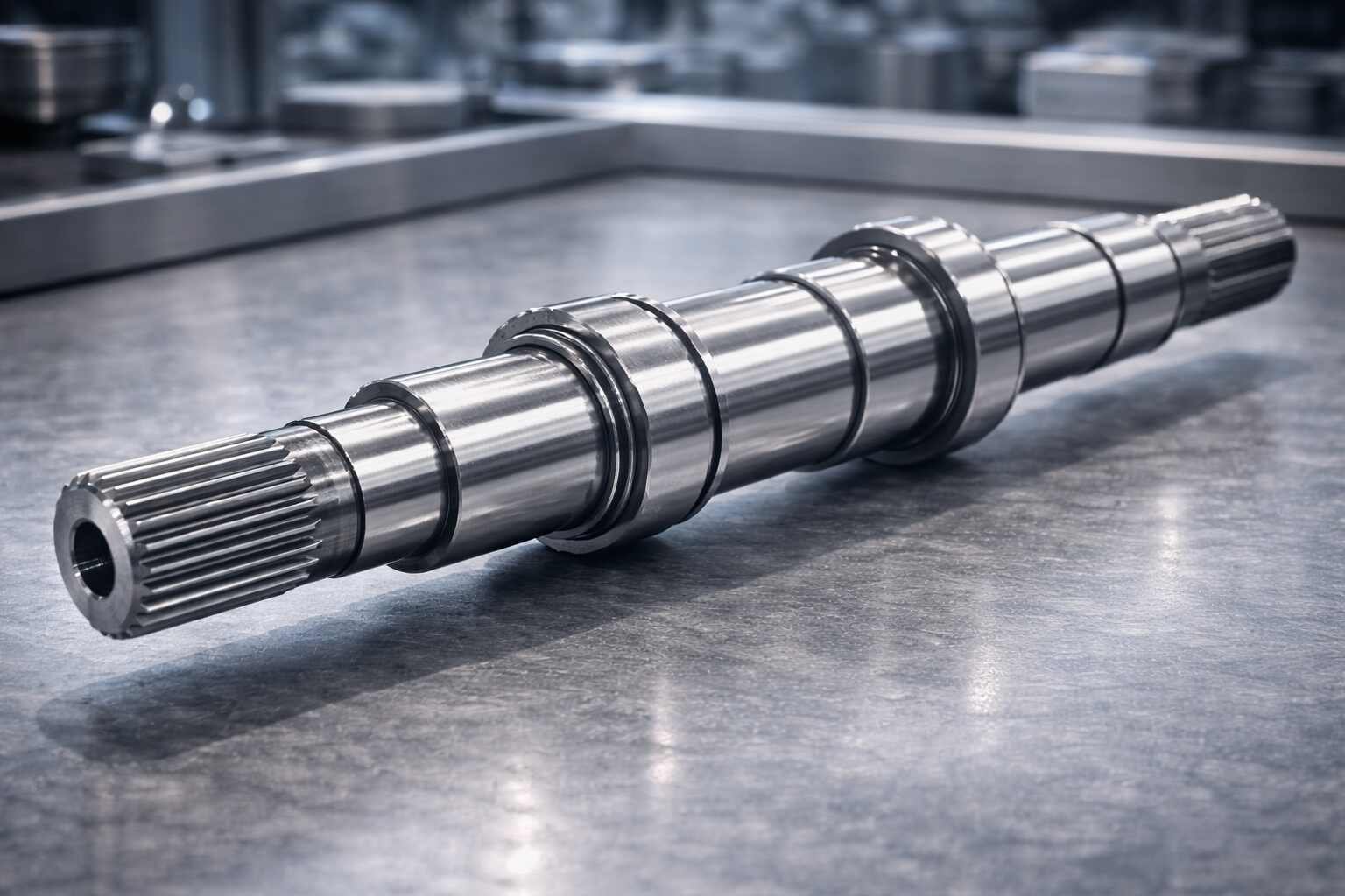
Photos are existing MW+ library illustrations. The featured shaft has features different from the example; none of the images establishes the specified keyway, material, customer or inspection result.
Contents
Define the connection and load case before shaft keyway design
In a parallel keyed connection, the shaft, hub and key form one load path. Published research distinguishes torque-transfer assessment from shaft fatigue verification and identifies material and geometry interactions that a simple pressure calculation cannot fully represent. [3]
For this guide, use a review sheet with separate entries for normal running torque, startup, braking, reversal and a jam or overload condition. State whether each entry is measured, supplied by the drive designer or assumed. Assign an owner to missing information. This is a recommended engineering workflow, not a prescribed universal load factor.
Also record the mating component, shaft diameter, usable hub length, assembly direction and required axial restraint. Treat the key calculation as one task within that assembly review. Do not approve bearing seats, shaft bending strength or the axial-retention arrangement simply because the key passes a preliminary torque check.
A useful drawing-review question is: “Which released requirement does this calculation demonstrate?” If the answer is only steady torque, keep reversing service and abnormal events open. The example below uses a chosen torque multiplier to expose a sensitivity; it does not select that multiplier for any real machine.
Specify keyway dimensions, shaft key tolerance and mating fit
Use the actual key and mating-hub specification
Ganter’s DIN 6885-1 extract lists a 12 × 8 mm key for its 40 mm shaft entry. In that diagram, the shaft radial depth is labelled t4 and equals 5 mm; the dimension across the remaining shaft section is t3 = d − t4 = 35 mm. Other references use different depth symbols, so transfer the physical dimension, not its letter alone. [1]
The worked example adopts that nominal section but defines its own symbols below. It does not reproduce a complete standard drawing. Confirm the key form, length convention, permitted corner geometry, depth limits and full governing specification before release. Check the actual mating-hub drawing rather than assuming every catalog hub uses the same arrangement.
Do not turn a fit label into an unspecified tolerance
The same Ganter extract pairs shaft/hub width classes as P9/P9 for tight seating, N9/JS9 for loose seating and H9/D10 for sliding. These are options within that source’s convention, not permission to choose one class for every application. [1]
Our drawing-review recommendation is to record the key width limits and both keyway width limits numerically after selecting the applicable fit. Keep the shaft-to-hub bore fit as a separate interface. Ask the assembly owner which member must retain the key and which movement, if any, is intended.
For an independent tolerance-arithmetic illustration, assume a key width of 11.970–12.000 mm and a slot width of 11.980–12.010 mm. Minimum slot-minus-key is 11.980 − 12.000 = −0.020 mm; maximum is 12.010 − 11.970 = +0.040 mm. These invented limits permit both interference and clearance. They are not the numerical conversion of any fit class listed above and are not a recommended production callout.
Use a transparent key shear and bearing-pressure screening model
The elementary model converts torque into a tangential force at shaft radius d/2, then divides that force by a shear area and separate bearing areas. The linked university treatment gives these equations. Here they are written with an explicit N·m-to-N·mm conversion and separately defined effective contact heights. [2]
- Td: assumed design torque, N·m; d: shaft diameter, mm.
- b: key width, mm; Le: effective supported length, mm.
- cs and ch: assumed effective loaded-face heights at shaft and hub respectively, mm.
Force: F = 2 × 1000 × Td / d, in newtons.
Average key shear: τ = F / (b × Le), in N/mm² = MPa.
Average bearing pressures: ps = F / (cs × Le); ph = F / (ch × Le), in MPa.
Define effective dimensions from the actual engaged geometry. For the idealized example, assume the nominal side heights are fully available and the supported straight length is known. Do not silently substitute overall key length or full hub width for Le. Record exclusions such as end relief or incomplete overlap as drawing-review assumptions.
The resulting pressures are averages, not peak contact stresses. Research on keyed connections discusses nonuniform pressure and the influence of hub geometry, fit and loading. Treat this simple model as screening rather than a complete strength-verification method. [3]
Worked example: a shear pass can hide a hub-bearing shortfall
All operating inputs and acceptance limits in this example are hypothetical. Only the nominal 40 mm shaft, 12 × 8 mm key section and 5 mm shaft depth are taken from the cited Ganter entry. The assumed effective heights are 5 mm on the shaft side and 3 mm on the hub side, with no deduction for corner relief. Actual contact geometry requires review. [1]
| Input | Value | Evidence status |
|---|---|---|
| Shaft diameter d; key b × h | 40 mm; 12 × 8 mm | Nominal chart selection, not a released design. |
| Assumed effective heights cs; ch | 5 mm; 3 mm | Idealized geometric assumptions. |
| Effective supported length Le | 40 mm | Assumed; must be established from overlap. |
| Running torque; chosen multiplier | 180 N·m; 1.5 | Assumed illustration, not application guidance. |
| Allowable shear; shaft-side bearing; hub-side bearing | 60; 120; 100 MPa | Invented screening limits, not material properties. |
The chosen design torque is 180 × 1.5 = 270 N·m. The force is 2 × 1000 × 270 / 40 = 13,500 N. The shear area is 12 × 40 = 480 mm²; shaft-side bearing area is 5 × 40 = 200 mm²; hub-side area is 3 × 40 = 120 mm².
| Screening check | Calculated value | Assumed limit | Result under assumptions only |
|---|---|---|---|
| Key shear | 13,500 / 480 = 28.125 MPa | 60 MPa | Below the assumed limit. |
| Shaft-side bearing | 13,500 / 200 = 67.5 MPa | 120 MPa | Below the assumed limit. |
| Hub-side bearing | 13,500 / 120 = 112.5 MPa | 100 MPa | Exceeds the assumed limit. |
The example therefore remains unresolved. A low shear value cannot cancel the hub-side shortfall. With running torque alone, the hub-side average would be 75 MPa; applying the chosen multiplier changes that result to 112.5 MPa. The point is to expose the load assumption, not to endorse the multiplier.
No grade, heat treatment or fatigue limit has been assigned. The assumed stress limits deliberately differ between interfaces to demonstrate why the complete material pair matters. A real calculation needs justified allowables, applicable factors and the responsible engineer’s chosen assessment method.
Check which change addresses the governing requirement
Rearranging the same screening equations gives an effective-length threshold for each assumed limit: F/(bτallow) for shear, F/(csps,allow) for shaft-side bearing and F/(chph,allow) for hub-side bearing.
The example yields 18.75 mm, 22.5 mm and 45 mm respectively. Thus the hub-side requirement controls this simplified length comparison. At 45 mm, its average equals the invented 100 MPa limit exactly; that equality provides no additional margin. At an assumed 50 mm engagement, the arithmetic gives 90 MPa.
Those two lengths are sensitivity cases, not recommended repairs. Before accepting either, check available hub engagement, the drawing’s permitted changes and the validity of the load-distribution model. Do not extrapolate uniform load sharing indefinitely as the key gets longer; real pressure distribution requires an applicable joint assessment. [3]
Our recommended review note is: “Hub-side preliminary check unresolved; compare approved geometry alternatives and validated material limits.” Avoid a note saying only “use stronger key.” That proposal has not explained how it changes the assumed hub-side allowable or the shaft’s remaining verification.
Plan keyway machining access with the complete shaft
Sandvik Coromant identifies width, depth, length and machine configuration as tool-selection inputs. Its keyway-slotting guidance describes roughing with an undersized end mill followed by finishing the sides, addressing cutter deflection rather than assuming a one-pass slot has ideal walls. [4]
For a manufacturing review, supply an end view and a longitudinal section showing the keyway relative to shoulders, journals and hub engagement. Ask the supplier to identify cutter entry, holder clearance, support and inspection access. Mark any proposed relief as an approval item, not an automatic change to the customer drawing.
Keep a record of the intended finished state. If the route includes heat treatment or a surface operation, identify which dimensions are accepted afterward and who owns any allowance. This recommendation makes the order reviewable; it does not assert a particular finishing or heat-treatment capability at MW+.
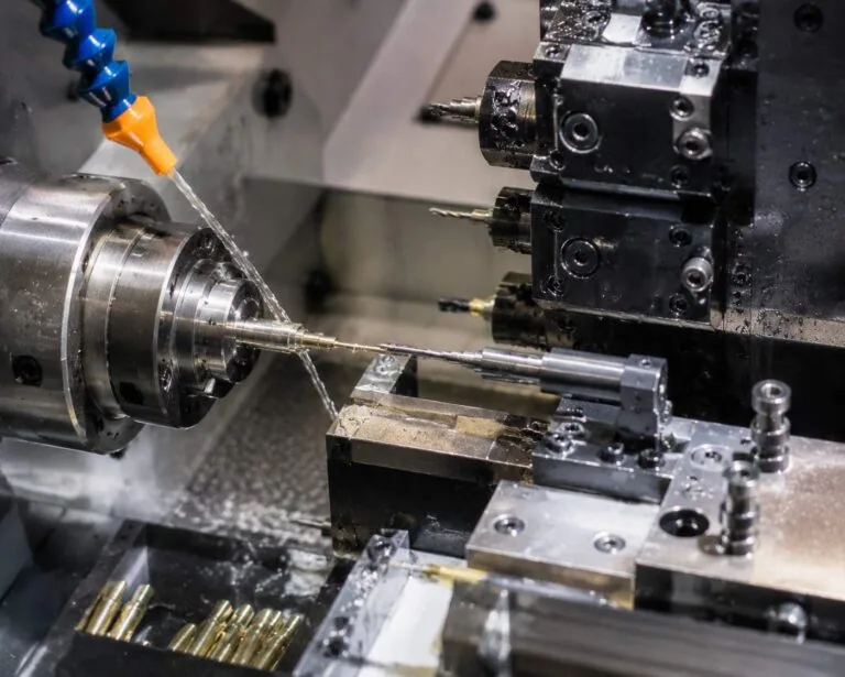
Use the shaft-turning service information when reviewing the journals and shoulders alongside the keyed feature. Request a coordinated route rather than assuming the separate turning and slotting requirements are interchangeable.
Build an inspection record around the released requirements
The following is a recommended inspection-planning framework, not a claim that a particular measurement was performed. Agree the method, datum setup, acceptance limits and reporting format before ordering. A value in a report should answer a named drawing requirement.
Record slot width at agreed axial positions, the defined radial-depth dimension, effective overlap, axial location, corner condition and any specified orientation to other features. Separate the slot-width result from the fit assessment: the latter also needs the key and mating-slot limits.
Include an assembly-review entry for seating and access where required by the design owner. If selective fitting or rework is proposed, obtain approval and preserve the revised limits. Do not let an undocumented “fits by hand” observation replace dimensional acceptance.
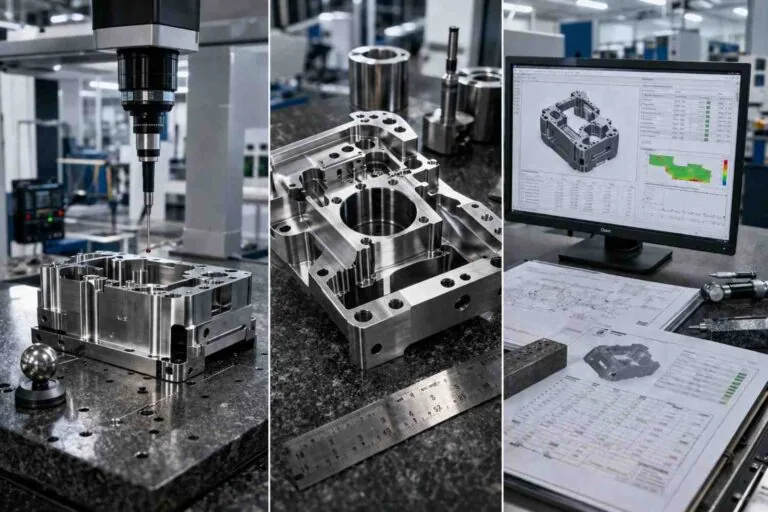
Shaft keyway design release checklist
| Review item | Evidence to retain | Keep open when |
|---|---|---|
| Loads | Approved torque cases and factor basis | Startup, reversal or overload remains unspecified. |
| Geometry | Matched shaft, key and hub drawings | Depth symbols or engagement are ambiguous. |
| Fit | Key and both slot limits; bore fit separately | The intended assembly behavior is undefined. |
| Strength | Key, contact, shaft and hub assessments | Only the elementary shear calculation is complete. |
| Manufacturing | Approved access and finished-state requirements | A relief or process allowance lacks approval. |
| Acceptance | Agreed dimensional and assembly evidence | No owner or criterion exists for an open requirement. |
Frequently asked questions
Does a standard key size establish torque capacity?
No. A dimension selection is not the complete load verification. Keep geometry, torque-transfer assessment and shaft fatigue review distinct. [3]
Can I assume half the key height carries hub-side bearing?
Use the actual supported face. The elementary equations distinguish shaft-side depth from the height projecting into the hub; an equal-half assumption is not universal. [2]
Which shaft key tolerance should I put on the drawing?
Select it with the key and mating hub, then record the applicable limits. The Ganter chart presents different class pairings for different seating intentions, rather than one class for all connections. [1]
Does increasing key length solve the example?
It lowers the calculated average in this assumed uniform model, but does not close the real assembly review. Available engagement, load distribution, justified allowables and the remaining component checks still need assessment. [3]
Is this a tested MW+ case study?
No. It is an illustrative application guide. No customer drawing, manufacturing record, torque test, measured improvement or approved production result is claimed.
Prepare the complete shaft-and-keyway machining enquiry
Use this review to prepare a coherent specification for machined mechanical components: the shaft, keyed interface and mating requirements should be understandable together. Retain bearing-fit decisions with their applicable bearing guidance; the bearing housing fits worked example addresses that separate assembly question.
For review through MW+ CNC project support, include the drawing revision, model, approved material and condition, quantities, keyway limits, journal requirements and inspection plan. Identify unresolved engineering questions explicitly. The MetalWorksPlus company overview provides company context without replacing the part-specific enquiry.
Ask for confirmation of the proposed manufacturing scope and any exclusions. A clear quotation should not be treated as evidence that the application’s torque, fatigue or safety requirements have already been validated.