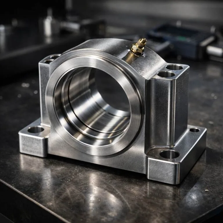
GD&T symbols identify the geometric requirement on a drawing: the permitted form, orientation, location, profile or runout of a feature. Read each symbol together with its tolerance zone, any material modifier, datum references and the drawing’s governing standard. A symbol on its own is not a complete manufacturing or inspection instruction. [1] [2]
This guide is for engineers, product developers and procurement teams reviewing precision machined parts. It explains how to turn a callout into a plain-language requirement, distinguish similar controls and check a supplier’s interpretation. The numerical example is hypothetical and is not an MW+ customer project, test result or capability promise.
Scope: the examples use a simple ASME-style drawing convention and millimetres. Apply the actual standard and edition named on your released drawing. ASME and ISO GPS share much of their visual language but differ in important implementation details, including datum treatment and the envelope principle. Do not transfer a chart’s defaults into an order without checking its scope. [12]
Contents
- A reliable reading sequence
- GD&T symbols and their functions
- Reading a feature control frame
- Datums and basic dimensions
- Controls that look similar
- Worked example: position at MMC
- Inspection evidence to request
- Drawing review checklist
- Frequently asked questions
- Preparing the machining enquiry
- Technical references
Read GD&T symbols in a consistent sequence
Start with the released drawing, not an isolated screenshot. ASME Y14.5 defines a system of symbols, rules and requirements for drawings and digital product definitions. Its scope is broader than a symbol chart, so a chart should serve as a recognition aid rather than replace the product definition. [1]
Recommended review sequence: identify the part revision and units; find the controlled feature; name the characteristic; describe the zone; apply the stated modifier; identify the datum sequence; then write the requirement in a sentence. Use this sequence for every critical callout in a drawing review.
For example, ask “Does this requirement constrain the surface itself, the bore’s axis, or the position of a hole pattern?” before discussing how to measure it. KEYENCE’s feature-control-frame guide distinguishes the characteristic symbol, zone information, modifiers and datum references; its datum guide also shows why the placement of the datum indication matters. [2] [3]
A useful review note records both the reading and any open question: “Bore position relative to the named mounting references; confirm whether acceptance applies after the specified finish.” That question is a recommendation for this workflow, not an additional tolerance silently imposed on the drawing.
GD&T symbols: what the main characteristics control
The table gives short recognition cues for common characteristics. The text names are authoritative for this guide; displayed characters are visual aids and may differ from your CAD font. Use the issued drawing’s actual glyph, attachment and standard for acceptance. The summaries below are paraphrased from the linked manufacturer references, not a reproduction of a standards table.
| Characteristic | Recognition aid | Meaning and review question |
|---|---|---|
| Straightness | Straight line | Limits deviation of a line or derived axis, depending on the indication. Which element is controlled? [4] |
| Flatness | Parallelogram | A surface fits between parallel planes. No datum reference is needed. [4] |
| Circularity / roundness | Circle | Controls circular cross-sectional form. Do not read it as location about a datum axis. [4] |
| Cylindricity | Circle between slanted lines | Controls cylindrical surface form between coaxial cylinders, without a datum. [4] |
| Parallelism | Parallel lines | Controls orientation relative to a datum. Which reference establishes the direction? [5] |
| Perpendicularity | Right-angle sign | Controls orientation at a right angle to a datum. Read the specified zone shape. [5] |
| Angularity | Angle sign | Controls orientation at the specified theoretical angle relative to a datum. [5] |
| Position | Crosshair | Controls a feature’s location; a diameter sign indicates a diametrical zone. [7] |
| Profile of a line | Arc | Controls the indicated cross-sectional profile within an envelope. [6] |
| Profile of a surface | Arc with baseline | Controls the indicated surface profile, rather than only a section. [6] |
| Circular runout | Single arrow | Limits variation at individual circular sections when rotated about the datum axis. [8] |
| Total runout | Double arrow | Limits variation over the specified surface during rotation about the datum axis. [8] |
Do not treat this list as permission to replace an unfamiliar legacy callout. Our recommendation is to refer a disputed symbol to the responsible drawing authority, record the governing edition and obtain a released clarification. A supplier’s convenient interpretation should not become an undocumented design change.
How to read a feature control frame
A feature control frame groups the characteristic, tolerance value and relevant zone or modifier information with any datum references. Datum references are read in their stated left-to-right priority, not rearranged alphabetically. Some controls do not need datums. [2] [4]
Illustrative callout in words: Position; diameter 0.20; maximum material condition; datum A; datum B; datum C. This is a verbal reading aid, not a manufacturing-ready drawing or a substitute for proper CAD annotation.
| Element | Reading | Practical check |
|---|---|---|
| Characteristic | Position | Identify the controlled hole or pattern. |
| Zone | Diameter 0.20 mm | Do not treat it as separate ±0.20 mm X and Y limits. |
| Modifier | MMC on the controlled feature | Read the hole size limits before calculating any allowance. |
| References | A, then B, then C | Locate the actual datum features in that priority. |
| Complete requirement | Frame plus drawing context | Check basic dimensions, feature extent and acceptance condition. |
Zone diameter is different from radial offset: for a centred circular zone of diameter 0.20 mm, its radius is 0.10 mm. That is elementary geometry applied to this hypothetical example. The manufacturer’s position reference supports the use of a diameter zone. [7]
Datums and basic dimensions provide the reference
A datum is an ideal reference; a datum feature is the real surface or feature used to establish it. A simulator, such as a sufficiently precise plate or mandrel, can help establish that reference from the real part. These terms describe different things. [3]
Basic dimensions define the theoretically exact geometry used with geometric tolerances. Their function is different from a conventional size limit. The SME teaching material illustrates basic dimensions alongside datum reference frames and feature control frames. [12]
Consider an illustrative plate whose underside is datum feature A, long side is B and end is C. Our proposed review question is whether those references represent how the plate actually locates in its assembly. If the assembly locates from two dowel holes instead, ask the designer to explain the chosen datum scheme before approving the inspection setup.
As a recommended handoff practice, send a labelled drawing view that identifies every reference surface and ask the supplier to describe its alignment. Keep manufacturing fixture choices separate from the drawing’s acceptance references. Resolve any proposed substitution through documented engineering approval.

Distinguish controls that answer different questions
Flatness versus parallelism
Flatness constrains the surface’s own form without a datum. Parallelism constrains orientation relative to a datum. A surface can therefore meet a form requirement while having an unacceptable orientation to a separate reference. [4] [5]
For an illustrative spacer, use separate questions: “Is this face sufficiently flat?” and “Is it oriented correctly to the locating face?” Do not answer both merely by reporting a thickness at one point. The suggested review method is to identify which drawing requirement each reported measurement addresses.
Circularity versus runout
Circularity concerns sectional form; runout concerns variation during rotation about a specified datum axis. Total runout evaluates the specified surface more broadly than circular runout at individual sections. They are different controls, not interchangeable words for roundness. [4] [8]
For a hypothetical rotating sleeve, first state whether the concern is sectional shape or behaviour about its mounting reference. Ask the drawing authority to select the appropriate requirement. Do not add runout merely because the component looks rotational.
Line profile versus surface profile
Line profile concerns the indicated section; surface profile concerns the indicated surface. For either, read the defined profile, controlled extent and references before interpreting the requirement. [6]
Our recommendation is to mark the intended inspection sections or coverage in the review package. A result for one section should not be presented as a complete inspection of a surface requirement without an agreed basis.
Worked example: a hole position requirement at MMC
Hypothetical inputs: a hole has size limits of 8.00–8.10 mm, with position diameter 0.20 mm at MMC relative to A, B and C. Assume a simple cylindrical hole, fixed datum alignment, no datum material modifiers and no composite or projected-zone requirement. All sizes and deviations below are invented teaching inputs.
MMC describes the feature’s greatest material condition: for this hole it is the smallest allowed diameter, 8.00 mm. With the applicable MMC requirement, departure from that condition can increase the allowed geometric tolerance; the separate size limits still apply. [9]
Suppose the illustrative measured hole size is 8.06 mm. Size departure is 8.06 − 8.00 = 0.06 mm. The example’s allowed diametrical position tolerance becomes 0.20 + 0.06 = 0.26 mm. This arithmetic applies the cited size-departure principle to our inputs; it is not a production measurement.
| Item | Input or calculation | Result |
|---|---|---|
| MMC size | Smallest permitted hole | 8.00 mm |
| Assumed hole size | Teaching input | 8.06 mm |
| Size departure | 8.06 − 8.00 | 0.06 mm |
| Allowed position | 0.20 + 0.06 | Diameter 0.26 mm |
| Assumed centre offsets | ΔX = +0.07; ΔY = −0.04 | mm |
| Diametrical deviation | 2 × √(0.07² + 0.04²) | 0.1612 mm, rounded |
The last row is the diameter of a centred circle reaching the hypothetical point, derived from the Pythagorean theorem. Under this simplified two-dimensional check, 0.1612 mm is below 0.26 mm. At MMC with no size departure, it would also be below the example’s base 0.20 mm allowance.
Boundary: one centre point does not establish a real bore’s complete axis condition. KEYENCE’s position inspection guide discusses measurements at different bore depths. Our example assumes the axis is parallel to its intended direction and the same offsets apply through the controlled length; a tilted or irregular real bore requires the applicable full evaluation. [10]
Do not add this allowance to an unrelated flatness or surface-finish requirement. Do not use it to accept an 8.11 mm hole: that would violate this example’s explicit size limit. Where the actual drawing includes datum modifiers or other zone requirements, obtain a complete standard-based interpretation rather than extending this simplified calculation. [9]
Turn the callout into an inspection question
Position measurement requires evaluation relative to the specified references. Gauges and CMM methods can serve different inspection needs; the manufacturer’s guide describes both and highlights multi-depth bore measurements. Our recommendation is to agree the method before production, including which characteristics a functional gauge actually verifies. [10]
Measurement coverage also matters. KEYENCE notes that point selection can change flatness results and discusses increasing measurement points. Do not interpret the instrument’s name alone as proof of complete coverage. [11]

Recommended inspection record: drawing and revision; characteristic ID; requirement; datum alignment; evaluated feature extent; actual result and units; instrument/method; measurement coverage; applicable size and modifier calculation; and agreed acceptance rule. Request clarification if the report supplies only “pass” without enough detail to connect it to the callout.
For a bore, separate the size result from the geometric result. For a datum-related characteristic, identify how the reference was established. For the worked example, record the assumed 8.06 mm size and 0.26 mm allowance separately from the calculated 0.1612 mm deviation so another reviewer can reproduce the reasoning.
Our existing CMM inspection report guide addresses report review in more detail. Keep this symbol-reading guide focused on interpreting the requirement; use the report guide for the evidence package.
A GD&T drawing review checklist before quotation
The checklist is an editorial recommendation, not a standards compliance certificate. Protolabs notes that excessive constraint and unnecessarily tight tolerances can increase manufacturing cost and restrict process choices. Specify the functional need, then ask for a feasible manufacturing and inspection route. [13]
| Review item | Record | Escalate when |
|---|---|---|
| Drawing baseline | Revision, units and governing standard/edition | Files conflict or the convention is unclear. |
| Controlled feature | Surface, axis, section or pattern and its extent | The attachment leaves the target ambiguous. |
| Datum scheme | Reference features and priority | Manufacturing and inspection propose different references. |
| Zone and modifier | Zone shape, value and permitted allowance | A modifier is being inferred rather than specified. |
| Functional reason | Mating or performance requirement | A tolerance has no explained design purpose. |
| Acceptance condition | Stage and surface condition at inspection | Finishing or assembly requirements are unresolved. |
| Evidence | Inspection method and report expectations | The supplier cannot explain its evaluation. |
For critical precision machined components, send this completed review with the model and drawing. Use the product page to identify the component scope; retain the drawing as the actual technical requirement. Avoid assuming a published tolerance headline guarantees every geometry, material or measurement condition.
Frequently asked questions about GD&T symbols
What does a GD&T symbol tell me?
It identifies the geometric characteristic. The frame and drawing provide the value, zone and applicable references or modifiers. Read the complete instruction rather than assigning a meaning from the symbol alone. [2]
Does flatness need a datum?
A surface flatness control does not require one. If the question is orientation to another reference, examine the appropriate orientation requirement instead. [4] [5]
Does diameter 0.20 mean ±0.20 in both directions?
No. A diametrical position zone has the specified full diameter. For the guide’s centred circular example, diameter 0.20 means radius 0.10, by geometry; it is not a square coordinate band. [7]
Does MMC allow a hole outside its size limits?
No. The size limits remain mandatory. The applicable geometric allowance can increase with departure from MMC inside those limits. [9]
Can I use the same symbol chart for ASME and ISO drawings?
Use it for recognition only after checking its scope. The systems have important implementation differences despite similar notation. Apply the standard and edition stated by the drawing. [12]
Should every feature receive the tightest available control?
That is not our recommendation. Start from function and agree an inspectable requirement. Excessive constraint can affect process options and cost; a tighter-looking drawing is not by itself a better specification. [13]
Prepare the machining enquiry from the drawing requirements
When asking MetalWorksPlus to review a component, include the released drawing, matching model, material and finish specification, quantities and unresolved interpretation questions. Identify the critical interfaces and explain what they do in the assembly.
Use the CNC machining project review to discuss how those requirements translate into a machinable and inspectable part. Ask for confirmation of feasibility and the inspection scope for your actual geometry. For the documentation discussion, our quality assurance page is a useful next destination; agree the project-specific evidence in writing.
These links identify published MW+ offerings, not evidence of a particular certification, numerical capability or completed project. The practical next step is a clarified technical package, with agreed requirements rather than unverified assumptions.
Technical references and example boundaries
The sources below support the definitions and technical principles cited near the relevant text. Manufacturer learning guides simplify some rules; the released drawing and its governing standards remain the basis for acceptance. ASME’s public page confirms scope; this article does not claim access to the complete paid standard.
- ASME: Y14.5 Dimensioning and Tolerancing.
- KEYENCE: Feature Control Frame.
- KEYENCE: What Are Datums?.
- KEYENCE: Form Tolerance.
- KEYENCE: Orientation Tolerance.
- KEYENCE: Profile Tolerance.
- KEYENCE: Location Tolerance.
- KEYENCE: Run-out Tolerance.
- KEYENCE: Maximum Material Condition.
- KEYENCE: Measuring True Position.
- KEYENCE: Measuring Flatness.
- SME: Fundamentals of GD&T, Part I.
- Protolabs: Fine-Tuning Tolerances for CNC Machined Parts.
The review sequence, enquiry checklist and inspection-record suggestions are original editorial recommendations. Numerical inputs are hypothetical; calculations are shown for reproducibility. Existing MW+ media are used as illustrations, not as proof of the example or customer performance. No customer project, search volume, ranking result or production improvement is claimed.