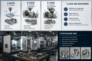
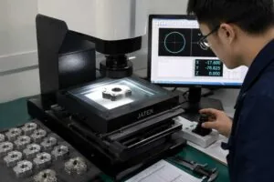
A CMM inspection report turns “the supplier says the part is good” into evidence you can act on: every controlled feature on the drawing, with its nominal, measured value, deviation and a verdict against the tolerance band.
This guide is for whoever has to approve or reject the shipment: what a usable report contains, how the machine’s own accuracy is qualified, how to check a position result by hand, and when a CMM report is the wrong thing to ask for.
Key takeaways
- A report is evidence only if it names the drawing revision, the datum frame and, per feature, nominal, tolerance band, measured value and deviation. A pass/fail column alone is not one.
- A CMM verifies the controls defined by ASME Y14.5 and ISO 1101 — position, profile, runout — but not surface roughness; an Ra callout also needs a profilometer trace.
- The machine’s own accuracy is qualified against ISO 10360-2 for length and ISO 10360-5 for probing. Ask for the reverification report, not a calibration sticker.
- ISO 14253-1 sets the rule near a limit: uncertainty comes out of the zone before conformance is proven, so a 0.002 mm deviation measured with 0.004 mm of uncertainty proves nothing.
- MW+ holds general machining to ±0.01 mm against ISO 2768-m, precision features to ±0.005 mm and critical features to ±0.001 mm, capability tracked to Cpk ≥1.67.
- What is a CMM inspection report?
- How does a CMM measure a machined part?
- What must a CMM inspection report contain?
- Which GD&T controls a CMM verifies
- Worked example: checking a true position result yourself
- How do you know the CMM itself is accurate?
- Reading a marginal result: accept, deviate or reject
- Which inspection document do you actually need?
- When a CMM report is the wrong thing to ask for
- How MW+ runs CMM inspection
- Frequently asked questions
What is a CMM inspection report?
A CMM inspection report is a dimensional record produced by a coordinate measuring machine that lists each controlled feature on a drawing with its nominal, measured value, deviation, specified tolerance and a pass or fail result — objective evidence generated from probe coordinates rather than an operator reading a scale.
A certificate of conformance says the supplier believes the part conforms; the CMM inspection report is the data behind it. Auditors under ISO 9001:2015 and AS9100D accept the certificate only when the records behind it are retrievable.
MW+ ships a certificate of conformance, a CMM inspection report and material certificates with every order; a buyer who has to ask for the data pays for the measurement twice.
How does a CMM measure a machined part?
A coordinate measuring machine moves a probe through a calibrated three-axis volume and records the X, Y and Z coordinate of each contact point. Software fits geometric shapes to those point clouds, builds a coordinate system from the drawing’s datums, then compares each fitted feature against nominal geometry. Three consequences explain most disputes over inspection data.
The datum scheme drives the result
A CMM measures position relative to the datum reference frame the programmer established. Take a different face as datum A than the drawing intends and true position on every hole changes, so a good part reads out of tolerance. Check the datum letters and their order against the feature control frames before disputing a result.
Point density changes what you can see
A circle measured with four touch points reports a diameter but almost nothing about roundness; a scanned circle of several hundred points reports form as well as size. Where a drawing carries circularity or profile, the report should state the points taken and the mode used.
Temperature is a real variable
Aluminium 6061-T6 expands roughly 23 micrometres per metre per degree Celsius, so on a 200 mm part a 5 °C difference between shop floor and metrology room shifts a length by about 23 micrometres — more than twice a ±0.005 mm band. Tight-tolerance measurement therefore happens in a controlled room after the part has soaked, and the temperature belongs on the report.
What must a CMM inspection report contain?
A CMM inspection report must contain the part number and drawing revision measured against, the datum reference frame used, and per controlled feature a balloon identifier, nominal, tolerance band, measured value and deviation. Anything less cannot be audited, because a reviewer cannot map each number back to a drawing requirement. The right-hand column is what should make you send a report back.
| Report field | Why it matters | Red flag |
|---|---|---|
| Drawing number and revision level | Confirms the revision actually measured | Revision blank or unrecognised |
| Datum reference frame (A, B, C) | Every position and orientation result depends on it | Missing, or ordered differently to the feature control frame |
| Balloon or item number per feature | Maps each number to a drawing callout | Free-text feature names such as “hole 3” |
| Nominal, upper and lower limit, measured value, deviation | The core evidence; a verdict hides how close the feature ran | Pass/fail column only |
| Number of points taken per feature | Separates a size check from a form check | Absent on a form or profile control |
| Measurement temperature | Thermal expansion bites at ±0.005 mm and below | Absent on a tight-tolerance report |
| Equipment ID and calibration due date | Establishes traceability | No ID, or a lapsed calibration date |
Which GD&T controls a CMM verifies
Geometric dimensioning and tolerancing is the drawing language specifying how far a feature may deviate in form, orientation and location, defined by ISO 1101 and, in North American practice, ASME Y14.5. A CMM verifies most of these controls directly because they are defined relative to datums rather than point-to-point. This table shows which callouts need one.
| Control | What the CMM measures | Datums required | Can a hand tool verify it? |
|---|---|---|---|
| Size (diameter, length) | Fitted diameter or distance | No | Yes — micrometer or bore gauge |
| Flatness | Spread between two parallel planes | No | Partly — surface plate and indicator |
| Perpendicularity, parallelism | Orientation of an axis or plane to a datum | Yes | Partly, with fixturing |
| True position of holes | Actual axis versus theoretical location | Yes | No |
| Profile of a surface | Deviation from the nominal model | Usually | No |
| Circular and total runout | Radial or axial variation about a datum | Yes | Partly — bench centres and indicator |
| Surface roughness (Ra) | Not measured by a touch probe | n/a | Profilometer required |
The last row is the one most often missed: a drawing calling out Ra 0.8 needs a profilometer trace as well as the CMM report. MW+ produces Ra 3.2 µm as-machined, Ra 0.4 µm fine-machined and Ra 0.1 µm polished, verified separately, because specifying a surface finish in Ra is a different discipline.
Worked example: checking a true position result yourself
Position is the control buyers most often misread, because the report prints one diameter while the evidence underneath is two coordinate deviations and a size. Take a hole specified Ø6.000 +0.050 / −0.000 with a positional tolerance of Ø0.100 at maximum material condition, to datums A, B and C. The report gives a measured diameter of 6.030 mm and an axis at X = +0.018 mm, Y = −0.024 mm from its theoretically exact location.
- Combine the two deviations into a radial distance. r = √(0.018² + 0.024²) = √(0.000324 + 0.000576) = √0.000900 = 0.030 mm.
- Convert radius to a diametral value. Position zones are cylindrical, so the reported deviation is 2r = 0.060 mm. Forgetting this doubling is the commonest mistake in a position dispute.
- Calculate the bonus tolerance. Maximum material condition for a hole is its smallest size, 6.000 mm; the hole measured 6.030 mm, so bonus = 6.030 − 6.000 = 0.030 mm.
- Add the bonus to the stated tolerance. Available positional tolerance = 0.100 + 0.030 = 0.130 mm.
- Take uncertainty out of the zone. With an expanded uncertainty of 0.004 mm on the axis location, the zone in which conformance can be proven shrinks to 0.130 − 0.004 = 0.126 mm.
- Compare. 0.060 mm sits inside 0.126 mm, so the feature conforms with 0.066 mm of margin.
Remove the MMC modifier and there is no bonus: the zone is 0.100 mm, uncertainty reduces it to 0.096 mm, and the same part passes with 0.036 mm of margin. The part did not change; the drawing modifier did. That is why a report printing only “TP 0.060 — PASS” is weaker evidence than one printing X, Y and actual size — you cannot tell whether the pass leaned on bonus tolerance a tighter-running lot will not have.
How do you know the CMM itself is accurate?
A CMM is qualified by acceptance and reverification testing against the ISO 10360 series. ISO 10360-2:2009 covers length measurement, stating a maximum permissible error of the form E0,MPE = A + L/K, in micrometres with L in millimetres — which is why a machine’s error is a function of measured length, not a single number. ISO 10360-5:2020 covers the probing system, reporting probing form and size errors in discrete-point and scanning modes.
Acceptance testing happens once, at installation. Reverification repeats it at an interval the user sets, and that is the test that protects you: it shows the machine still performs to the specification it was bought against. Traceability then runs from the artefacts used, through an accredited laboratory, to a national measurement standard.
| Question to ask a supplier | Document that answers it | Reference |
|---|---|---|
| Was the machine accepted against a published performance spec? | Acceptance test report | ISO 10360-2 for length, ISO 10360-5 for probing |
| Is it still performing to that specification? | Reverification report and the interval used | ISO 10360-2 / ISO 10360-5 |
| Are the artefacts behind the test traceable? | Calibration certificates for gauge blocks and ball bars | Lab accredited to ISO/IEC 17025, chain ending at NIST or equivalent |
| What is the uncertainty at my feature size? | Uncertainty budget for the measurement task | NIST Technical Note 1297 |
| How are conformance decisions made near a limit? | Written decision rule, agreed up front | ISO 14253-1:2017 |
The working convention is that the measuring system should be roughly ten times finer than the tolerance it verifies, four times being the practical floor. A ±0.005 mm feature cannot be signed off on an instrument carrying a couple of micrometres of its own uncertainty, which is why tight-tolerance CNC precision parts are verified on a CMM in a controlled room. Layering in-process gauging with CMM verification at first article and lot sampling is what CNC machining quality control means across MW+ CNC machining services.
Reading a marginal result: accept, deviate or reject
Most reports are neither clean passes nor obvious failures: a feature sits within a few micrometres of a limit, and the decision costs schedule or money. ISO 14253-1 gives the default rule — whoever makes the claim carries the uncertainty. A supplier proving conformance works inside a zone reduced by the expanded uncertainty; a customer proving non-conformance must be outside it by the same margin. Between those guard bands neither claim is provable. Work through a marginal result in this order.
- Confirm the datum scheme on the report matches the drawing. A mismatched datum frame is the most common cause of a false reject on position callouts.
- Compare the deviation against the stated uncertainty. A 1 µm deviation from a system with roughly 2 µm of uncertainty is not a measurable non-conformance.
- Look at the trend across the sample, not the single part. Features drifting one way indicate tool wear, and the rest of the batch will be worse.
- Ask whether the tolerance is functional or inherited from a legacy drawing. On a clearance hole, a formal concession is cheaper for both parties than a rework cycle.
- Record the decision as a written concession against that lot. A verbal acceptance destroys the audit trail the report existed to create.
Which inspection document do you actually need?
The document to request depends on the stage of the programme, not the industry. A prototype needs dimensional confirmation of the features you will test; a production launch needs a formal first article inspection; an automotive series programme needs PPAP. Asking for all three on a prototype adds cost without information.
| Programme stage | Document to request | What it proves | Availability at MW+ |
|---|---|---|---|
| Prototype, 1–10 pieces | CMM inspection report on critical features | The parts you will test match the drawing | Ships with every order |
| Any shipment | Certificate of conformance and material certificates | Attestation, material identity and heat number | Ships with every order |
| Production launch or process change | First article inspection to AS9102 | Every characteristic ballooned and measured | On request, quoted per programme |
| Automotive series supply | PPAP Level 3 | Full package, capability study and control plan | On request, quoted per programme |
| Ongoing series production | Lot sampling report plus capability data | The process is still centred and capable | Included with production runs |
MW+ tracks capability to Cpk ≥1.67 on controlled characteristics and holds ISO 13485, IATF 16949, ISO 9001:2015, AS9100D and NADCAP accreditation. When qualifying a supplier, capability data tells you more than one part’s report: it describes the process, not one sample.
When a CMM report is the wrong thing to ask for
A CMM inspection report is the wrong request when the question is not dimensional, when the part deflects under probe force, or when the feature is easier to control statistically than to measure piece by piece. Requesting one anyway adds cost without reducing risk.
| Situation | Better request | Why |
|---|---|---|
| Drawing calls out Ra 0.8 or a cosmetic finish | Profilometer trace and signed finish sample | A probe measures neither roughness nor appearance |
| Thin-wall or elastomeric parts under 1 mm wall | Non-contact optical or CT | Probe force deflects the surface |
| High-volume turned parts, simple diameters | SPC charts and capability indices | Lot trend data beats five sampled pieces |
| Assembly fit is the real concern | Functional gauge or mating-part check | Every feature can pass while the stack-up fails |
| Internal geometry a probe cannot reach | Industrial CT scan | Closed cavities are unreachable by a stylus |
There is a scale limit too. Full inspection of every piece is realistic at low volume; at tens of thousands of units the right control is a capable process with sampled verification. Agree the inspection plan at quotation, with the discipline that keeps a tight tolerance budget honest.
How MW+ runs CMM inspection
MW+ operates a 15,000 m² facility at No. 39 Xishi Road, Hewan Community, Guangming, Shenzhen, founded in 2015, with 60+ CNC machining centres and 120+ engineering and quality professionals serving 50+ countries. Inspection is sequenced, not bolted on.
- Incoming material is checked against its mill certificate before release.
- Operators gauge in-process to keep the machine centred in the band, not merely inside it.
- The first part off a new setup is measured in full before the run continues.
- Lot sampling continues through the run, catching tool wear as a trend rather than a scrapped batch.
- Reports are signed off and ship with the conformance and material certificates.
Quotes are returned within 24 hours; express prototypes run in 48 hours, standard prototypes in 3–5 business days and volume production in 10–15 business days, to 1,000,000+ units with no minimum order quantity. Inspection runs alongside production rather than extending those windows, whether the work sits in multi-axis machining or elsewhere in the CNC machining capabilities list.
Frequently asked questions
Does a CMM inspection report add cost or lead time to my order?
It ships with every MW+ order at no separate charge, and inspection runs in parallel with production, so it does not extend the quoted window. What adds cost is a formal first article inspection to AS9102 or a PPAP Level 3 submission: both require every drawing characteristic to be ballooned and documented, and both are quoted per programme.
Why did a feature pass at the supplier and fail at our incoming inspection?
Usually a different datum reference frame, a temperature difference between the two metrology rooms, different probing strategies, or two labs applying different decision rules at the limit. Compare the datum letters and their order, then the stated temperature, then the points per feature — a four-point circle and a scanned circle report different diameters on the same part.
Can I ask for 100% CMM inspection on a production run?
You can, and for safety-critical features it is sometimes right, but price it before you specify it. Inspection time scales linearly with volume, so at production quantities the cost can approach the machining cost. For most programmes a capable process tracked to Cpk ≥1.67 with sampled verification protects you better per dollar.
What tolerance can MW+ actually hold and verify?
MW+ holds general machining to ±0.01 mm against ISO 2768-m, precision features to ±0.005 mm and critical features to ±0.001 mm. Verifying the ±0.001 mm band needs a temperature-controlled room and a soaked part, so mark on the drawing which features genuinely require it — it changes fixturing and inspection cost.
Is a certificate of conformance enough without the measurement data?
For low-risk commercial parts, often yes. For regulated work, no: a certificate is an attestation, and an auditor will ask for the records behind it. Under AS9100D and ISO 13485 the supplier retains those records anyway, so requesting them costs nothing and gives your quality team a defensible file.
What should I send so the inspection matches what I need?
Send a 3D model in STEP, IGES or native SolidWorks with a 2D drawing in PDF or DXF carrying the tolerances, datum scheme and critical characteristic markings. The model defines nominal geometry; the drawing defines what must be inspected and against which datums. Without it the inspection program runs on a default assumption, and that is where disputes begin. Send both when you request a CNC machining quote.