Surface finish Ra is the parameter most drawings use to control texture, and it is also the parameter most drawings state badly. A bare “Ra 0.8” in a title block, applied to every surface on the part, is the single most expensive line an engineer can add to a print.
This guide is about the specification itself: what a complete Ra callout contains, where it goes on the drawing, which cutoff to state, and how to decide which surfaces need a number at all. It assumes you already know roughly what roughness is and now have to write it down so a machine shop can quote it and an inspector can verify it.
Key takeaways
- A complete Ra callout states five things: the parameter, the value with its unit, the cutoff length, the surface it applies to, and whether material removal is required or prohibited.
- Ra was defined in ISO 4287:1997, which ISO has replaced with ISO 21920-2:2021. Both are still quoted on live drawings, so name the one your drawing follows.
- Always state the unit. Ra 63 µin is 1.6 µm and routine; Ra 63 µm is an as-cast surface. The unit is roughly a 40× difference.
- Conventional cutoff is 0.8 mm for Ra between 0.1 and 2.0 µm and 2.5 mm above that. Without it, two labs can measure the same surface and report different numbers.
- On a turned surface the theoretical roughness is Ra ≈ f² / (32 rε), so feed and nose radius set the floor before the machine is even chosen.
- MW+ delivers Ra 3.2µm as-machined, Ra 0.4µm fine-machined and Ra 0.1µm polished. Each step is a separate operation, so apply it per surface, not as a blanket note.
- What Ra is, and what the number on the drawing controls
- How do you specify Ra on a drawing?
- Which cutoff length and measurement method should you state?
- What Ra is achievable by process?
- Worked example: what feed and nose radius do to a turned Ra
- Which Ra value does your application actually need?
- Five specification mistakes that cost money
- When a tighter Ra is the wrong specification
- How MW+ handles surface finish callouts
- Frequently asked questions
What Ra is, and what the number on the drawing controls
Ra is the arithmetic mean deviation of a surface profile from its centreline, measured over a defined sampling length and expressed in micrometres or microinches. Ra is a single averaged number, which is why it is easy to specify and easy to misuse: two surfaces with the same Ra can have very different peak heights and very different sealing behaviour.
Which standard your drawing names matters more than it used to. Ra and the related profile parameters were defined in ISO 4287:1997, which ISO has replaced with ISO 21920-2:2021; the indication rules moved to ISO 21920-1:2021. Drawings citing the older standard are still in wide circulation, and the two are not identical in their default rules, so state which one governs. On drawings following the ASME convention the parameters are defined in ASME B46.1.
Ra, Rz and Rmax: which parameter belongs on the drawing
Ra averages the whole profile. Rz averages the largest peak-to-valley heights across the sampling lengths. Rmax is the single largest peak-to-valley height in the evaluation length. Because Ra averages, it hides isolated defects: a machining scratch across a sealing face can leave Ra unchanged while Rmax doubles.
Specify Ra for general texture control, and add Rz or Rmax on any surface where a single deep valley is a functional failure — dynamic seal running surfaces, high-cycle fatigue surfaces, and sealing faces for elastomer gaskets. Specifying Ra alone on those surfaces controls the wrong thing.
How do you specify Ra on a drawing?
A complete Ra specification states five things: the parameter symbol, the numeric value with its unit, the cutoff or sampling length, the specific surface it applies to, and whether material removal is required, permitted or prohibited. The surface texture symbol that carries these is defined in ASME Y14.36 on ASME drawings and in ISO 21920-1 on ISO drawings. Run this checklist against any drawing before it goes out for quotation.
| What the callout must state | Example | What happens if you omit it |
|---|---|---|
| Parameter | Ra (add Rz where peaks matter) | The shop assumes Ra; an inspector may report Rz and the numbers will not agree |
| Value and unit | Ra 0.8 µm | A µm/µin mix-up changes the requirement by roughly 40× |
| Cutoff or sampling length | Cutoff 0.8 mm | Two labs filter differently and report different Ra for the same surface |
| Which surface | Leader line to the bore, not the title block | The value is applied to every face and the part is quoted several times over |
| Material removal condition | Machining required, or machining prohibited | An as-cast face may be machined unnecessarily, or left when it should be cut |
Per-surface callouts beat a blanket note
Put the general finish in the title block at the level most of the part genuinely needs — usually Ra 3.2µm as-machined — then attach tighter callouts by leader line only to the faces that need them. This is the same logic as a general tolerance under ISO 2768, where a default class covers the drawing and individual features carry their own tighter values.
The failure mode is a title block reading “all surfaces Ra 0.8” on a milled housing with forty faces. It converts a single finishing operation into forty, and almost none of them do anything. Where the finish interacts with a datum or a form control, keep the texture callout next to the relevant feature control frame from ASME Y14.5 so the two are read together.
State the lay when direction matters
Lay is the dominant direction of the pattern left by the tool. On a rotating shaft running against a lip seal, a helical lay acts as a pump and can drive lubricant out of the joint even when Ra is within specification. If the surface slides, seals or rotates against another part, add the lay symbol rather than relying on Ra alone.
Which cutoff length and measurement method should you state?
State the cutoff whenever the Ra value is functionally critical, because the cutoff is the filter that decides what the instrument counts as roughness rather than waviness. The conventional values come from ISO 4288:1996, now carried forward in ISO 21920-3:2021: 0.8 mm for Ra between 0.1 and 2.0 µm, and 2.5 mm above that. Measurement is normally a contact stylus profilometer; optical instruments are used where a stylus would damage a soft or coated surface.
| Ra band (µm) | Ra band (µin) | Conventional cutoff (mm) | Usual instrument |
|---|---|---|---|
| 0.1 to 2.0 | 4 to 80 | 0.8 | Contact stylus profilometer |
| Above 2.0 to 10.0 | 80 to 400 | 2.5 | Contact stylus profilometer |
| 0.1 and below | 4 and below | 0.25 or as agreed | Optical or interferometric; stylus radius becomes limiting |
| Soft, coated or plated surfaces | Any | As agreed | Optical, to avoid marking the surface |
Two further points belong in the note rather than in a phone call after the parts arrive. Say how many measurements constitute acceptance and where they are taken, because Ra varies across a machined face. And if the value is tight enough to be arguable, require that the instrument carries calibration traceable to a national measurement institute — the NIST calibration services page describes what that chain is, and the same traceability question applies to every number on a CMM inspection report.
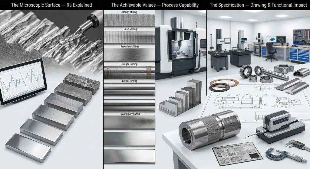
What Ra is achievable by process?
Standard CNC turning and milling reach Ra 3.2µm as a routine as-machined condition and Ra 1.6µm with controlled feeds and sharp inserts. Reaching Ra 0.4µm requires a dedicated fine-machining pass, and Ra 0.1µm requires polishing or grinding after machining. Check that the finish you are about to specify is compatible with the process you have in mind for that feature.
| Process | Typical achievable Ra (µm) | Typical achievable Ra (µin) | What limits it |
|---|---|---|---|
| Rough milling or rough turning | 6.3 | 250 | Feed per tooth and depth of cut |
| Standard CNC milling and turning | 3.2 to 1.6 | 125 to 63 | Insert nose radius, feed rate, rigidity |
| Fine machining pass | 0.8 to 0.4 | 32 to 16 | Tool wear and machine vibration |
| Reaming and honing (bores) | 0.8 to 0.4 | 32 to 16 | Bore straightness and tool condition |
| Cylindrical or surface grinding | 0.4 to 0.2 | 16 to 8 | Wheel grade and dressing interval |
| Polishing or lapping | 0.1 | 4 | Manual operation; hard to hold form at the same time |
| Wire EDM | 1.6 to 0.4 with skim passes | 63 to 16 | Number of skim passes; each adds machine time |
Two process notes matter when you write the callout. On a bore, a finish reachable in one operation by CNC turning services is far cheaper than the same number reached by reaming afterwards, so check the feature geometry before tightening the number. And on hardened material, cutting tools cannot reach a fine finish at all — wire EDM services with skim passes are the route, and each skim pass is priced separately.
Worked example: what feed and nose radius do to a turned Ra
On a turned surface the roughness left by the tool path is predictable before anything is cut. The theoretical arithmetic mean roughness is Ra ≈ f² / (32 rε), where f is the feed per revolution and rε the insert nose radius, both in millimetres; the result is in millimetres, so multiply by 1,000 for micrometres. Work an ordinary finishing pass through it.
- Start with the planned cut. Feed f = 0.15 mm/rev on an insert with nose radius rε = 0.8 mm. f² = 0.15 × 0.15 = 0.0225 mm².
- Divide by 32 rε. 32 × 0.8 = 25.6 mm, so Ra = 0.0225 ÷ 25.6 = 0.000879 mm = 0.88 µm.
- Compare with the drawing. Against an Ra 0.8 µm callout, the theoretical floor is already above the limit — before tool wear, vibration or built-up edge are considered. This cut cannot meet the print.
- Solve for the feed that would. Rearranged, f = √(Ra × 32 × rε). For Ra 0.4 µm = 0.0004 mm: f = √(0.0004 × 25.6) = √0.01024 = 0.101 mm/rev.
- Convert that to time. Axial cutting time scales inversely with feed, so dropping from 0.15 to 0.101 mm/rev makes the finishing pass about 0.15 ÷ 0.101 = 1.48 times longer — roughly 50% more cutting time on that surface.
- Buy some of it back with geometry. Raise the nose radius to 1.2 mm and f = √(0.0004 × 32 × 1.2) = √0.01536 = 0.124 mm/rev, so the pass is only about 1.21 times longer. A larger nose radius is the cheaper lever where the part is rigid enough to take the extra radial force.
Two cautions. The formula gives a floor, not a prediction: built-up edge, insert wear, workpiece deflection and chatter all push the measured value above it, which is why a shop plans the theoretical figure comfortably below the specified limit rather than at it. And a larger nose radius cannot exceed the corner radii your drawing allows, and increases deflection on thin or slender parts, so it is not free.
Which Ra value does your application actually need?
The Ra value your application needs is set by what the surface does, not by how good the part should look. Dynamic seal running surfaces and bearing journals need Ra 0.4µm or better. Static gasket faces and fatigue-critical surfaces are usually satisfied at Ra 0.8µm. General mating faces work at Ra 1.6µm, and clearance surfaces that touch nothing need no callout beyond the drawing default.
| Surface function | Ra (µm) | Ra (µin) | Add alongside Ra |
|---|---|---|---|
| Dynamic seal running surface | 0.2 to 0.4 | 8 to 16 | Rmax and lay direction — a helical lay pumps lubricant out |
| Bearing journal | 0.4 | 16 | Roundness and cylindricity controls |
| Static gasket or O-ring face | 0.4 to 0.8 | 16 to 32 | Rz, to catch single deep scratches |
| Fatigue-critical surface | 0.4 to 0.8 | 16 to 32 | Direction of machining marks relative to the load |
| General mating face | 1.6 | 63 | Flatness if the joint must be rigid |
| Bonded or painted surface | 1.6 to 3.2 | 63 to 125 | A minimum Ra, not a maximum |
| Clearance or non-functional face | 3.2 to 6.3 | 125 to 250 | Nothing; leave it at the drawing default |
Note the sixth row. On a bonded or painted face the requirement is a floor, not a ceiling, and it should be written as a minimum Ra. Writing “Ra 1.6 max” on a surface that needs a bonding profile specifies the opposite of what the design needs.
Five specification mistakes that cost money
- A blanket title-block value. One tight number applied to every surface turns one finishing operation into dozens.
- No unit. “Ra 32” is 32 µin on an ASME drawing and 32 µm on an ISO one. Write the unit every time.
- No cutoff. The supplier’s default filter and your inspector’s default filter can differ, and the argument happens after the parts ship.
- A finish the process cannot reach. Ra 0.4µm on a deep milled pocket with no access for a finishing tool forces a process change nobody quoted.
- Ra where Rz was meant. On a sealing face, Ra can pass while a single scratch fails the joint. Add Rz or Rmax.
All five are caught by one habit: read the drawing back as if you were quoting it, and ask what each callout forces the shop to do. A supplier offering CNC machining services should raise these at quotation rather than after the first article — the same review that catches an over-specified grade in a material cost review.
When a tighter Ra is the wrong specification
A tighter Ra is the wrong specification whenever the surface needs texture to do its job, or whenever roughness is not what is failing. Bonded joints, painted surfaces and lubricated sliding faces all perform worse on a mirror finish. And when a joint leaks, the cause is more often flatness, waviness or a burr than roughness average.
| Situation | Do not tighten Ra | Specify instead |
|---|---|---|
| Adhesive-bonded joint | A smoother surface reduces mechanical interlock | A minimum Ra and a surface preparation note |
| Painted or powder-coated face | Coating needs an anchor profile | A minimum Ra, and whether dimensions are before or after coating |
| Lubricated sliding surface | Polished surfaces hold less oil | An Ra band with upper and lower limits |
| Flange that leaks | Roughness is rarely the cause | Flatness, waviness and a deburr note |
| Anodised or plated part | The coating changes the measured texture | Whether Ra applies before or after the coating |
| Thin-wall or flexible part | A stylus can deflect the surface it measures | An optical method, and the measurement support condition |
| Cosmetic surface | Ra does not describe appearance | A named finish such as bead blast, with a boundary sample |
The last row is worth stating plainly. Ra is a functional parameter, not an appearance parameter. Two surfaces at the same Ra can look completely different depending on lay and process, so cosmetic requirements need a named finish and an agreed boundary sample, not a roughness number.
How MW+ handles surface finish callouts
MW+ operates a 15,000 m² facility at No. 39 Xishi Road, Hewan Community, Guangming, Shenzhen, founded in 2015, with 120+ engineering and quality professionals, 60+ CNC machining centres and 70+ material grades. MW+ delivers Ra 3.2µm as-machined, Ra 0.4µm fine-machined and Ra 0.1µm polished, and holds general machining to ±0.01mm to ISO 2768-m with ±0.005mm on precision features.
At quotation, every surface texture callout is reviewed against the feature it is attached to, and any that the specified process cannot reach — or that appear to have been applied by default — is flagged back to you. Quotes are returned within 24 hours; the CNC machining capabilities list sets out the process range, and tight-band work sits under CNC precision parts.
Every order ships with a certificate of conformance, a CMM inspection report and material certificates, under a quality system certified to ISO 9001:2015, AS9100D, ISO 13485, IATF 16949 and NADCAP. First article inspection to AS9102 and PPAP Level 3 are available on request, quoted per programme. Send a drawing in STEP, IGES, DXF, DWG, SolidWorks or PDF to request a CNC machining quote.
Frequently asked questions
My parts measured Ra 0.9 against a 0.8 requirement. Who is right?
Neither party can be right until the cutoff length, the number of traces and the trace locations are agreed, because Ra depends on all three. If the drawing did not state a cutoff, the supplier and your inspection lab may have filtered the same surface differently. Fix the drawing first, then re-measure both sets of parts under the stated conditions before rejecting anything.
Should I put the surface finish in the title block or on each surface?
Put a default in the title block at the level most of the part needs, typically Ra 3.2µm as-machined, and attach tighter values by leader line to individual surfaces. A blanket title-block value at a fine finish forces the shop to treat every face as a finishing operation, which is the most common way a texture callout inflates a quote.
Does a tighter Ra change my tolerance requirement?
Ra and dimensional tolerance are independent specifications, but they interact on cost. A finishing pass that improves Ra removes a small amount of material, so the roughing pass must leave stock for it and both operations must land inside the dimensional band. On a feature already at ±0.005mm — the band costed in budgeting for ±0.005 mm — adding a fine finish usually means an extra setup rather than an extra pass.
Can I specify Ra on an as-cast or as-extruded surface?
You can, but you must also state the material removal condition. If the drawing says machining is prohibited, the Ra value describes what the casting or extrusion process must deliver and belongs in the supplier agreement for that stock. If it says machining is required, you have specified a machining operation on a face you may not have intended to cut.
Does anodising or plating change the Ra I specified?
Yes. Anodising and plating build a layer on the surface and change the measured texture, usually toward a slightly rougher reading on anodised aluminium. State whether the Ra requirement applies before or after the coating, and whether the dimensional tolerance does too. Leaving both open is a common source of first-article disputes.
Why did my quote rise sharply when I moved from Ra 1.6 to Ra 0.4?
Ra 1.6µm is reachable within a normal machining pass, while Ra 0.4µm requires a dedicated fine-machining operation with slower feeds and a fresh tool, and on some features a grinding or honing step on a different machine. The step from 1.6 to 0.4 crosses a process boundary, so it adds an operation rather than a few seconds of cycle time.
Which standard should my drawing reference for surface texture?
On ISO-convention drawings, reference ISO 21920-1 and ISO 21920-2 for new work, or ISO 4287 if your document set is still built on it — and say which. On ASME-convention drawings, reference ASME B46.1 with the ASME Y14.36 symbol set when the drawing is otherwise dimensioned to ASME Y14.5. Mixing conventions on one drawing is legal but invites misreading, so state the governing standard in the notes and stay with it.