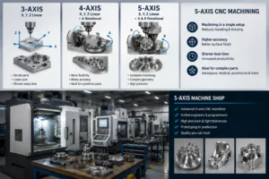
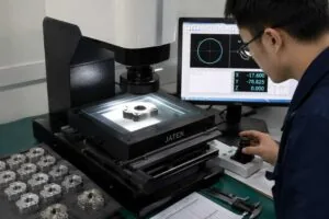
A ±0.005 mm callout does not simply make a part “more accurate”. It changes which budget lines the part carries: slower finishing passes, per-part inspection instead of sampling, a higher scrap allowance, and a longer first-article approval before the batch runs.
This guide is about budgeting for that, not about how tight tolerances are achieved. It covers what each cost line does at ±0.005 mm, how to decide which features genuinely need it, and how to compare two quotes that claim the same capability.
Key takeaways
- ±0.005 mm equals ±0.0002 inches, or 5 micrometers on each side of nominal.
- A tight tolerance adds four budget lines: finishing time, per-part inspection, scrap allowance, and first-article approval. Setup and inspection are charged per batch, so quantity changes the answer.
- Set the drawing default to ±0.01mm under ISO 2768-m and apply ±0.005mm only to features that mate, seal, locate or rotate.
- Where a clearance or interference is what matters, specify an ISO 286 fit designation rather than a symmetric band — it usually gives the shop more usable tolerance for the same function.
- MW+ holds precision features to ±0.005mm with a ±0.001mm floor, at a process capability of Cpk ≥1.67, and ships a CMM inspection report with every order.
- First article inspection to AS9102 and PPAP Level 3 are available on request and quoted per programme — budget them separately from the part price.
- What does ±0.005 mm actually add to the price?
- The tolerance ladder and where your features belong
- Which features actually need ±0.005 mm?
- Worked example: does the tight band actually buy you anything?
- How does material choice change a tight-tolerance budget?
- The inspection line item most buyers forget
- Why quantity moves a tight-tolerance quote more than a loose one
- When ±0.005 mm is the wrong specification
- What to ask before you trust a tight-tolerance quote
- Tight tolerance machining at MW+
- Frequently asked questions
What does ±0.005 mm actually add to the price?
A ±0.005 mm tolerance adds four distinct costs to a CNC part: a dedicated finishing pass at reduced feed, inspection of every part rather than a sample, a higher scrap allowance because a single out-of-band feature condemns the whole part, and a longer first-article approval before production releases. None of these is a percentage uplift on machining; each is a separate line you can budget and control.
Treat them as four levers, not one number. The table below states what each line does at ±0.005 mm and what you can change on the drawing to reduce it.
| Budget line | What changes at ±0.005 mm | How to control it |
|---|---|---|
| Machining time | A separate finishing pass at reduced feed and depth of cut, plus tool changes on a shorter interval | Limit the tight band to the features that need it |
| Inspection | Measurement moves from batch sampling to per-part CMM on the controlled features | Reduce the number of controlled features, not the tolerance on the ones that matter |
| Scrap allowance | One feature out of band scraps the part after all prior operations are paid for | Put tight features early in the sequence where possible, and avoid clustering them |
| First article approval | An FAI or PPAP cycle runs before the batch releases | Budget it once per part number, and reuse it across repeat orders |
| Fixturing | Purpose-built workholding to hold the part without distorting it | Design a stable datum surface the fixture can clamp on |
The tolerance ladder and where your features belong
A tolerance ladder is a mapping from tolerance band to the process, the inspection method and the typical use that goes with it. Every feature on your drawing sits on one rung, and the ladder is what tells you whether you are asking for something routine or something that needs a dedicated operation.
| Tolerance level | Achievable on | Typical use | Cost impact |
|---|---|---|---|
| ±0.1 mm | Any feature, any setup | Clearance holes, cosmetic edges, non-contact faces | None — this is the free rung |
| ±0.01 mm to ISO 2768-m | Most features machined in a single setup | The MW+ general machining default | Included in standard machining |
| ±0.005 mm | Rigid features, single setup, controlled measurement temperature | Bearing seats, sealing bores, locating faces, rotating fits | Adds a finishing pass and per-part inspection |
| ±0.001 mm | Short, rigid, well-supported features only | Critical fits on precision components | Adds a dedicated process and metrology plan |
The default rung matters most for the budget. ISO 2768 is the general tolerance standard that most drawings fall back on, and stating class m in the title block means every unmarked dimension carries a sensible band without a per-feature callout. MW+ holds general machining to ±0.01mm to ISO 2768-m and applies ±0.005mm to the features that carry it, with a ±0.001mm floor available on CNC precision parts.
Specify a fit, not a symmetric band
When what you actually need is a clearance or an interference between two parts, a symmetric ±0.005 mm on both members is usually the expensive way to get it. The limits and fits system in ISO 286 lets you place the tolerance zone where the function needs it, often giving each part a wider band than a symmetric split would.
The same logic applies to form and position. A profile or position control from ASME Y14.5, applied at maximum material condition, can release bonus tolerance that a plain ± dimension never gives you. This is the cheapest tolerance you will ever buy, because it costs only drawing effort.
Which features actually need ±0.005 mm?
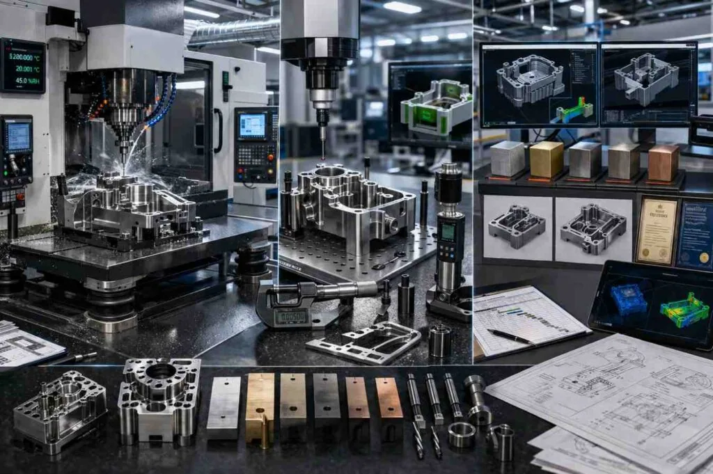
The features that genuinely need ±0.005 mm are the ones where a fit, a seal or a rotation depends on the dimension: bearing seats, sealing bores, press fits, locating diameters and datum faces that other parts index from. Everything else on a typical part — clearance holes, outside profiles, cosmetic faces, pocket depths that touch nothing — functions correctly at the drawing default.
| Feature | Needs ±0.005 mm when | Otherwise specify |
|---|---|---|
| Bearing seat | A rolling element bearing presses into it | An ISO 286 fit designation, which is usually cheaper |
| Sealing bore | An O-ring or lip seal runs in it | Diameter at the default plus a roughness callout on the sealing face |
| Locating diameter or datum face | Other parts index position from it | A position control referencing the functional datum |
| Rotating fit or spline | Concentricity governs vibration or wear | Runout relative to the axis, not a diameter band |
| Clearance hole | Never | ±0.1 mm, or the drawing default |
| Outside profile | Only where it mates | ISO 2768-m general tolerance |
| Overall length | Only where it stacks into an assembly | A tolerance stack analysis, then band the one dimension that needs it |
Run this check before you request a quote. The most common finding is that a drawing with a blanket tight band has three or four features that actually need it, which is a very different part to quote.
Worked example: does the tight band actually buy you anything?
Before tightening a dimension, check what it contributes to the assembly it feeds. Take three components stacked inside a housing pocket: each part is nominally 20.000 mm long and the pocket is nominally 60.200 mm deep, so the nominal gap is 60.200 − 60.000 = 0.200 mm. The design needs that gap to stay between 0.050 mm and 0.350 mm.
- Start with every dimension at ±0.050 mm. A worst-case stack adds the tolerances arithmetically: 0.050 × 4 = 0.200 mm. The gap then ranges 0.000 mm to 0.400 mm, which breaks both limits.
- Check the statistical case. Root-sum-square combines them as √(0.050² + 0.050² + 0.050² + 0.050²) = √0.010 = 0.100 mm, giving a gap of 0.100 mm to 0.300 mm. That passes, but only if all four processes are centred and capable.
- Tighten the obvious candidate. Put the pocket depth at ±0.005 mm and leave the three parts alone: worst case = (0.050 × 3) + 0.005 = 0.155 mm, so the gap runs 0.045 mm to 0.355 mm. A tenfold tightening of one dimension still fails, at both ends.
- Tighten the contributors instead. Halve the three parts to ±0.025 mm and leave the pocket at ±0.050 mm: worst case = (0.025 × 3) + 0.050 = 0.125 mm, giving 0.075 mm to 0.325 mm. That passes worst-case, with no feature below ±0.025 mm.
- Compare what you bought. Step 3 paid for a ±0.005 mm feature and solved nothing. Step 4 stayed on a rung the shop reaches without a dedicated finishing pass, and solved the problem.
What the arithmetic shows is that a stack is governed by the number of contributors, not by the tightest one. Two cautions before relying on step 2: root-sum-square assumes the contributors are independent and centred on nominal, which is what a capability index such as Cpk ≥1.67 exists to demonstrate, and it gives no protection if one supplier runs consistently to one side of its band. Worst-case is the safe assumption when you cannot see capability data.
How does material choice change a tight-tolerance budget?
Material changes how hard the same tolerance is to hold, because it changes cutting temperature, work hardening, springback and thermal expansion. Aluminum 6061-T6 and free-machining brass are the most forgiving at ±0.005 mm. Austenitic stainless steels work harden at the cut. Titanium and nickel superalloys hold heat in the cutting zone, so tool wear moves the dimension within a single batch.
| Material | Behaviour at a tight tolerance | What it forces |
|---|---|---|
| Aluminum 6061-T6 | Stable and easily cut; highest thermal expansion of the common grades | Control of measurement temperature on large features |
| Brass C360 | Free machining, low cutting force, excellent dimensional stability | Little beyond normal practice |
| Stainless 304 and 316L | Work hardens at the cut; gummy chips | Sharp tooling, consistent feed, more frequent tool changes |
| Titanium Grade 5 (Ti-6Al-4V) | Retains heat in the cutting zone; low thermal conductivity | Reduced speeds, high-pressure coolant, tighter tool-life control |
| Nickel superalloys such as Inconel 718 | Rapid tool wear moves the dimension within a batch | In-process gauging and scheduled tool replacement |
| Engineering plastics such as PEEK | Low stiffness and moisture-sensitive dimensions | Light cuts, conditioned storage, and a stated measurement condition |
The budget consequence is straightforward: the same ±0.005 mm feature is a routine finishing pass in aluminum or brass and a controlled process with in-process gauging in a superalloy. If the load case permits a more machinable grade, changing it reduces the cost of every tight feature at once, which is where a material cost review starts.
The inspection line item most buyers forget
At ±0.005 mm, measurement stops being an afterthought and becomes a scheduled operation with its own machine, its own operator and its own cycle time. A coordinate measuring machine measuring twelve controlled features on every part is a real per-part cost, and it belongs in your budget explicitly rather than buried in an overhead rate.
Two things make that measurement trustworthy. The instrument must carry calibration traceable to a national measurement institute — the NIST calibration services page describes what that chain looks like. And the process must demonstrate capability: MW+ holds process capability at Cpk ≥1.67, an index defined and worked through in the NIST/SEMATECH engineering statistics handbook. What that report has to contain to be usable as evidence is set out in this guide to CMM inspection reports.
First article inspection and PPAP are quoted separately
Every MW+ order ships with a certificate of conformance, a CMM inspection report and material certificates, included as standard. First article inspection to AS9102 and PPAP Level 3 are available on request and quoted per programme, because both are documentation packages produced once per part number rather than per piece.
Budget them as a one-off at programme start and amortise them across the life of the part number. Asking for a full FAI on a ten-piece prototype order and again on every repeat batch is one of the more expensive habits in precision procurement.
Why quantity moves a tight-tolerance quote more than a loose one
Setup, programming, fixture build and first-article approval are charged per batch, not per part. On a loose-tolerance part those are small; on a tight-tolerance part the fixture is purpose-built and the approval cycle is longer, so the per-batch component is large. That is why the price curve between prototype and production quantities is much steeper for precision work.
MW+ has no minimum order quantity and runs volumes to 1,000,000+ units, so the practical question is not whether a small order is possible but how you phase the programme. Quotes are returned within 24 hours; express prototypes ship in 48 hours, standard prototypes in 3–5 business days, and volume production runs in 10–15 business days. Prototype work is priced through CNC prototyping, where the setup dominates by design.
When ±0.005 mm is the wrong specification
A ±0.005 mm band is the wrong specification whenever the thing you actually care about is not a size. Leaks, vibration, binding assemblies and misaligned bores are usually failures of form, position or surface texture, and tightening a diameter fixes none of them. The same applies to the shape itself, where part geometry drives cost through tool access rather than through the tolerance band. Tightening the wrong control costs money and leaves the problem in place.
| Situation | Do not tighten the size tolerance | Specify instead |
|---|---|---|
| A flange joint leaks | Diameter is rarely the cause | Flatness, surface roughness and a deburr note |
| A rotating assembly vibrates | A diameter band does not control the axis | Runout and concentricity relative to a functional datum |
| Parts will not assemble | Each dimension may already be in tolerance | A tolerance stack analysis, then band the controlling dimension |
| A long, thin or thin-walled feature | The part deflects during cutting and measurement | A wider band plus a stated measurement support condition |
| A large aluminum feature | Thermal expansion exceeds the band across a temperature swing | The measurement temperature, referenced to 20 °C |
| The dimension crosses two setups | Re-fixturing error is added to the machining error | A position control between the features, not a size band on each |
| A plated or anodised feature | The coating changes the finished dimension | Whether the tolerance applies before or after coating |
There is also a scale case. Where the feature itself is very small, the limit is the process rather than the specification, and the right route is micro machining services or, for slender turned parts, Swiss machining, where the guide bushing supports the stock at the cut.
What to ask before you trust a tight-tolerance quote
- Which features did you quote at the tight band, and how many controlled dimensions did you assume?
- Is inspection per part or per batch at this tolerance, and is the CMM report included in the price?
- What process capability do you hold, and can you show a capability study on a comparable feature?
- Is the measuring equipment calibration traceable to a national measurement institute?
- Are FAI and PPAP included or quoted separately, and at which level?
- How many setups does the part need, and does any controlled dimension cross a setup boundary?
- What is the scrap allowance in this price, and who carries it on a repeat order?
A quote that cannot answer the second and sixth questions is not comparable with one that can. Ask both suppliers the same list before you compare numbers, whether you are buying CNC machining services or a single prototype.
Tight tolerance machining at MW+
MW+ is a precision CNC machining supplier operating a 15,000 m² facility at No. 39 Xishi Road, Hewan Community, Guangming, Shenzhen, founded in 2015, with 120+ engineering and quality professionals, 60+ CNC machining centres and 70+ material grades, serving customers in 50+ countries. MW+ holds general machining to ±0.01mm to ISO 2768-m, precision features to ±0.005mm, and a ±0.001mm tolerance floor, at Cpk ≥1.67.
The MW+ quality system is certified to ISO 9001:2015, AS9100D, ISO 13485, IATF 16949 and NADCAP, which means one supplier covers aerospace, medical, automotive and commercial programmes under a single system. Surface finish runs from Ra 3.2µm as-machined to Ra 0.4µm fine-machined and Ra 0.1µm polished.
Multi-face precision work runs through multi-axis machining to keep controlled dimensions inside a single setup. How those records are produced sits under CNC machining quality control. Send a drawing in STEP, IGES, DXF, DWG, SolidWorks or PDF to request a CNC machining quote.
Frequently asked questions
What is ±0.005 mm in inches, and how tight is that in practice?
A tolerance of ±0.005 mm equals ±0.0002 inches, or five micrometers either side of nominal. In practice it is tight enough that the temperature of the part at the moment of measurement matters, that the measuring instrument’s own uncertainty has to be accounted for, and that a feature crossing two machine setups is difficult to hold at all.
Why did tightening one dimension change my whole quote?
Because a tight dimension usually changes the inspection regime for the entire part, not just that feature. Once one dimension requires per-part CMM measurement, the part goes through the measuring machine every time, and the fixture may have to be rebuilt to hold the part without distorting it. The change is a step, not a proportional increase.
Can every material hold ±0.005 mm?
No. Aluminum, brass and steel hold it routinely on rigid features. Austenitic stainless work hardens at the cut, titanium retains heat in the cutting zone, and nickel superalloys wear tools fast enough that the dimension drifts within a batch. On those materials the same band is achievable but requires in-process gauging and scheduled tool replacement, which is a different cost structure.
How do I verify a supplier can actually hold the tolerance?
Ask for a process capability study on a comparable feature, a gauge repeatability and reproducibility study for the measuring method, and a sample first article inspection report. Certification tells you a system exists; the capability study tells you what that system delivers on a feature like yours. Ask for both, and ask on which machine the study was run.
Is a tighter tolerance ever cheaper than a looser one?
Occasionally, when the tighter specification removes an operation. Specifying a bore to a fit that a reamer produces in one pass can be cheaper than a wider band that leaves the process open and invites a slower interpolated route. It is the exception, not the rule, and it only appears when you talk to the supplier about process rather than dimensions.
Should I put a blanket tight tolerance on the drawing to be safe?
No. A blanket tight tolerance is the most reliable way to inflate a precision quote without improving the part, because it forces finishing passes and inspection on features that touch nothing. Set the general tolerance in the title block to ISO 2768-m, mark the functional features individually, and let the supplier price the difference so you can see it.
Budgeting for ±0.005 mm is mostly an exercise in restraint. Identify the handful of features where a fit, a seal or a rotation depends on the dimension, use fits and geometric controls where they give you more room, keep controlled dimensions inside one setup, and account for inspection and first-article approval as their own lines rather than as a mark-up.