







ISO 9001:2015 Certified · Shenzhen, China · Est. 2015
Precision Multi-Axis CNC Machining
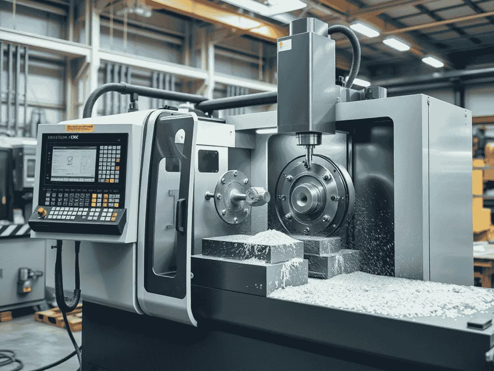
Multi-axis machining — 3-axis, 4-axis & full 5-axis simultaneous — to ±0.001mm to ±0.005mm for procurement teams and engineers who can't afford a bad batch. Prototype to production — 70+ materials, quoted within 24 hours, delivered DDP anywhere in the world.
Request a Quote- No MOQ — 1 to 100,000 pcs
- English-speaking engineers
- Global DDP Shipping
01 / Machining services
Multi-axis machining options
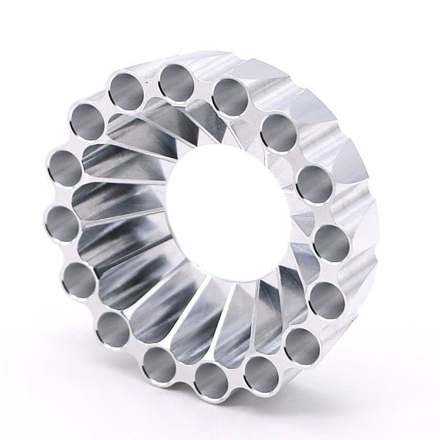
MW+ selects 3-axis, rotary 4-axis, indexed 3+2 or simultaneous 5-axis machining based on geometry and tolerances.
3-axis CNC milling
For plates, pockets, bores and prismatic parts with straightforward tool access. A practical starting point when added rotary motion would not improve the part.
4-axis machining
A rotary axis brings features around a part into reach. Indexed or coordinated motion is selected for radial holes, repeated faces and rotary components.
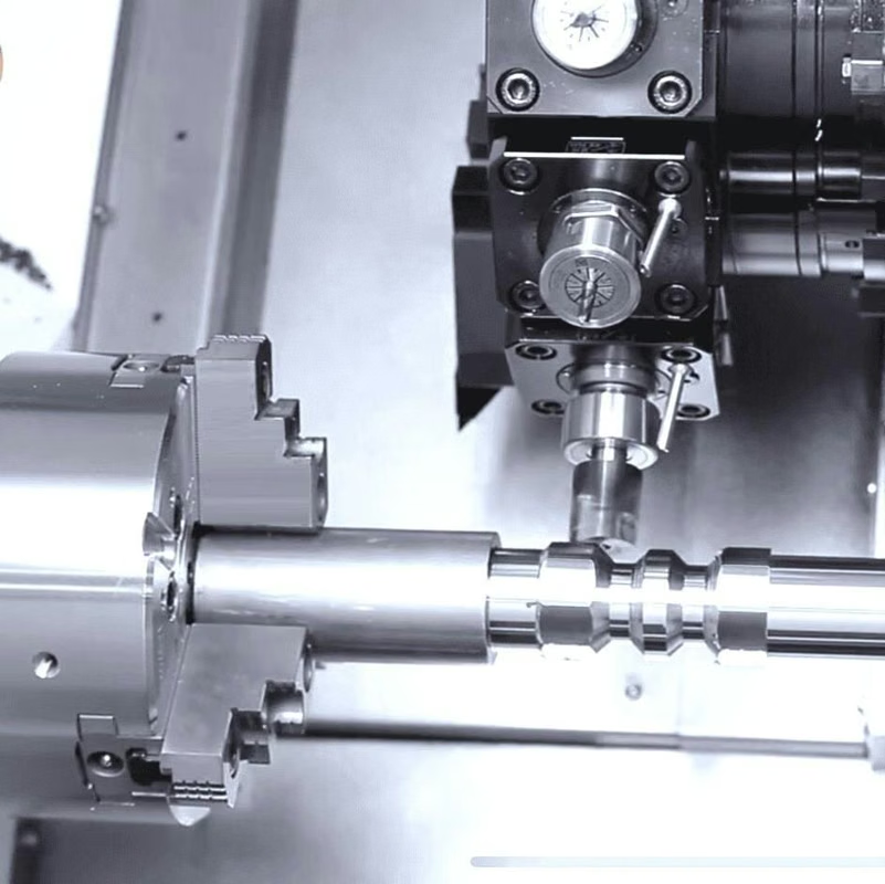
5-axis & indexed 3+2 machining
3+2 positions the workpiece before a 3-axis cut. Simultaneous 5-axis changes tool orientation during cutting for contoured surfaces and compound access. We specify which route your part needs.
Five axes do not guarantee a single setup. Clamping stock, underside access and inspection datums can still require repositioning. Photos illustrate machining and component examples.
02 / Components on drawing
Complex geometry.
Clear acceptance criteria.
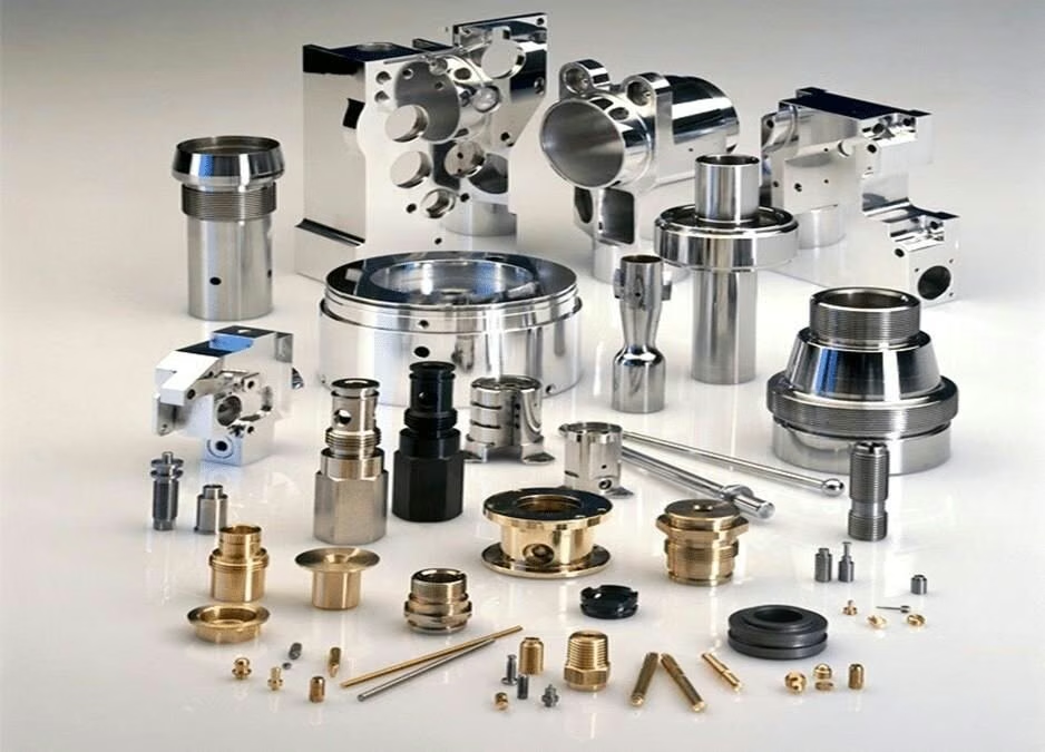
Custom multi-axis machined parts for OEM assemblies and industrial equipment. These component families show typical applications; every order follows an agreed drawing, material and inspection plan.
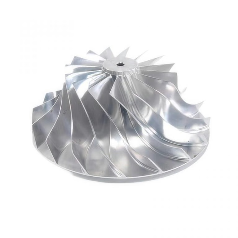
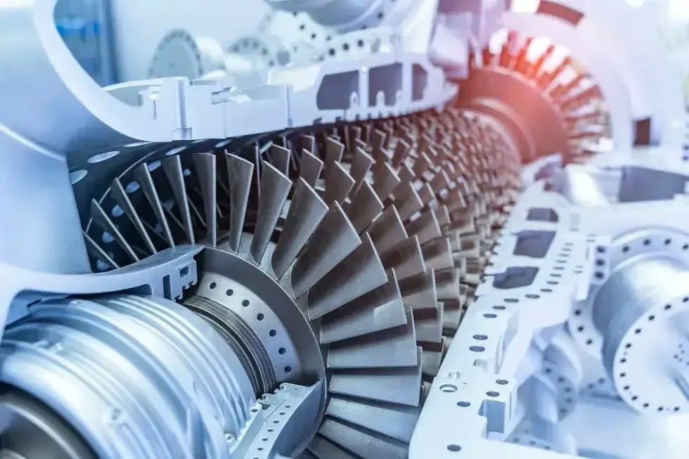
Impellers & contoured parts
Blade profiles, hub datums and tool access reviewed together. Specify balance requirements separately.
Discuss this component ↗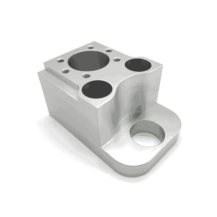
Valve bodies & manifolds
Cross ports, threads and intersecting passages. Define sealing faces, cleanliness and deburring requirements.
Discuss this component ↗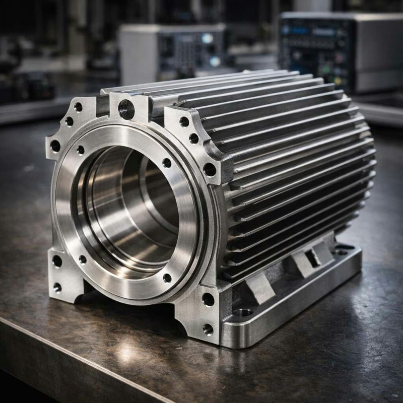
Precision housings
Bearing bores, mounting faces and side features. Control the relationship between assembly datums.
Discuss this component ↗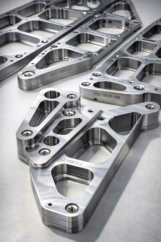
Structural brackets
Angled interfaces, pockets and weight reduction. Thin-wall rigidity and fixture support checked during DFM.
Discuss this component ↗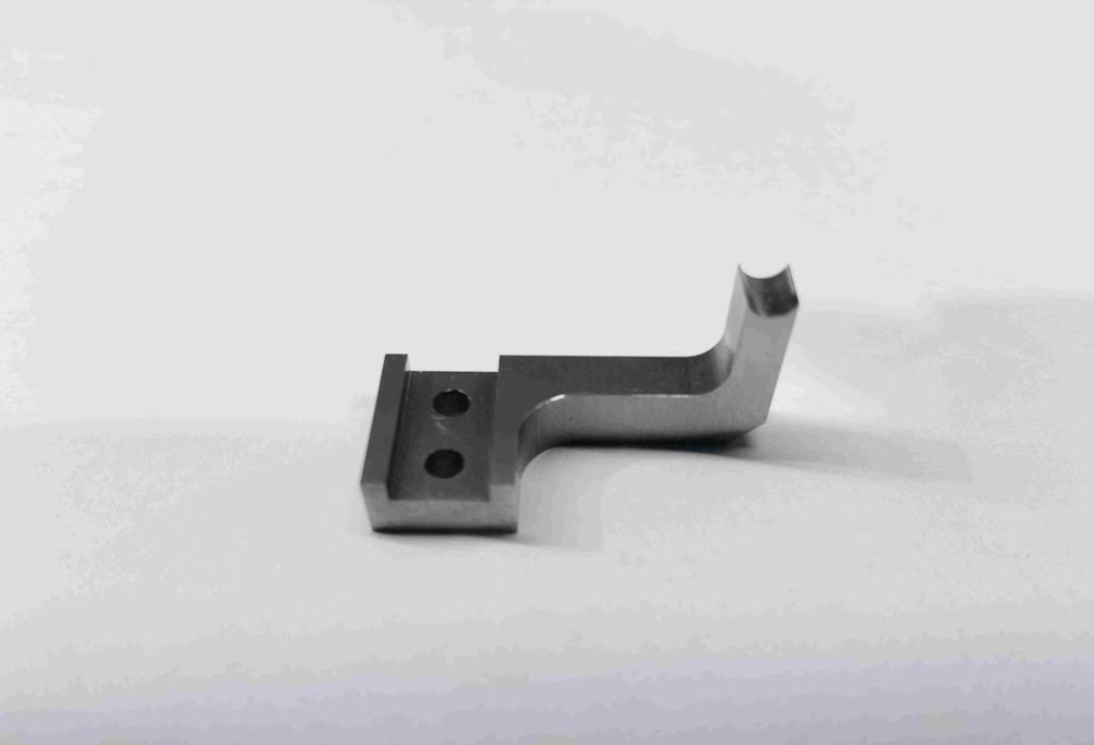
Mounts & fixture components
Locating surfaces, bolt patterns and repeatable assembly interfaces manufactured to your specification.
Discuss this component ↗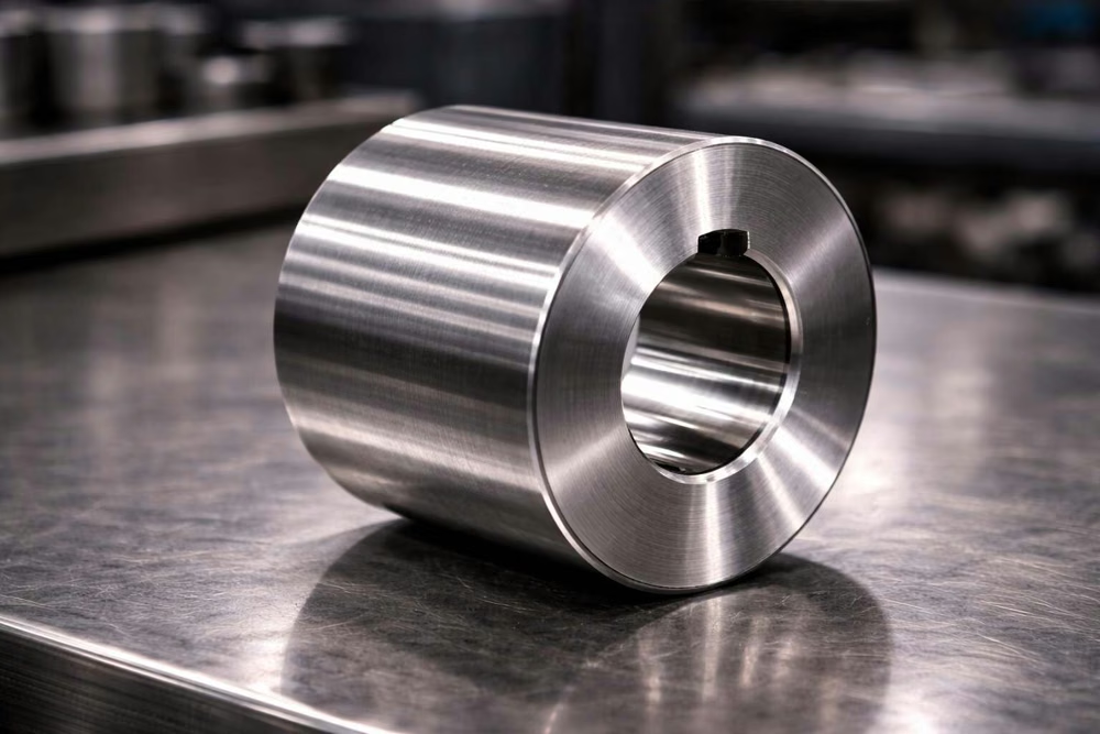
Rotary parts & gear blanks
Concentric features and radial details. Tooth cutting, heat treatment and final grinding are quoted separately when required.
Discuss this component ↗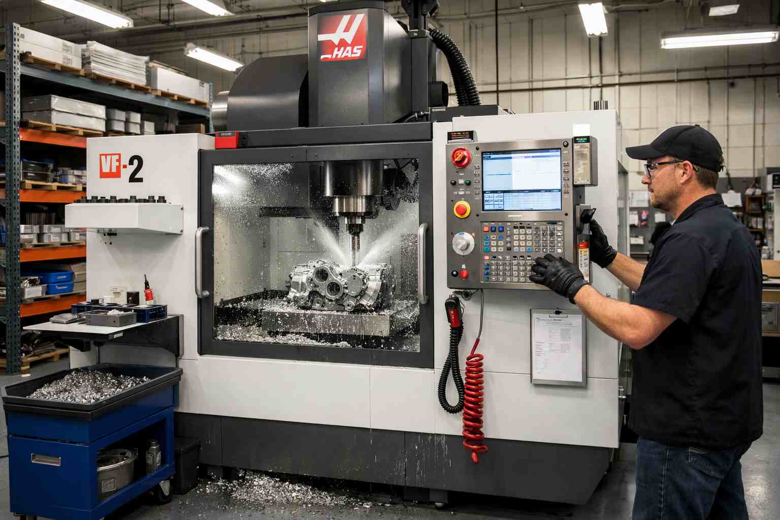
Beyond the catalogue
Any part you can draw
The component examples above are only a starting point. At MW+, we manufacture custom multi-axis machined parts from your drawing. Send a STEP file and a dimensioned drawing for an itemised quote, from a single prototype to repeat production. We confirm feasibility, material, quantity and lead time during the engineering review.
- One prototype or 100,000 precision parts, quoted from the same drawing
- 70+ materials, from 6061 aluminium to Inconel 718 and PEEK
- Reverse engineering from a sample part or a hand sketch
- Complete assemblies and finished components, not loose parts
- Free DFM review before anyone cuts metal, with cost notes
- NDA signed on request, and drawings stay on our own servers
Inside a multi-axis setup
When features on different faces must align, the setup plan matters as much as the number of axes. These examples show what to settle before machining.
Keep related features together
For a housing with two bearing bores, identify the common axis and mounting datum. Review whether both bores can be cut in one clamping or how to verify alignment after re-clamping.
Plan access and support
On a pocketed bracket, check holder clearance at angled faces and support for thin walls. Agree where the fixture may contact the part and which surfaces must stay clear.
03 / Technical review
Capability data
with the right context.
Use these published references to prepare an RFQ. Geometry, material condition, feature size, thermal stability and inspection method determine the final achievable specification.
| Reference | Published value |
|---|---|
| 3-axis typical tolerance | ±0.010 mm |
| Selected critical features, 4/5-axis | ±0.001–0.005 mm* |
| 3-axis travel, up to | 1,200 × 600 × 600 mm* |
| Spindle range across equipment | 12,000–24,000 rpm* |
*Reference only, subject to engineering review. Travel is not a guaranteed part envelope; rotary clearance and fixturing reduce usable space. The quoted tolerance applies to identified features, not every dimension.
| Requirement | Review point |
|---|---|
| GD&T & datums | Identify functional fits and datum sequence. |
| Surface finish | Specify Ra, location and measurement direction. |
| Coated dimensions | State before/after coating acceptance. |
| Inspection | Agree method, sampling and reporting. |
Machine positioning accuracy and repeatability are not finished-part tolerances. General drawing tolerances do not replace explicit limits on critical features.
Process reference: Haas explains the distinction between indexed 3+2 and simultaneous 5-axis machining.
Read the machine-builder guide ↗04 / Materials & surfaces
The grade matters.
So does the finish.
Specify an exact grade and condition rather than a material family. We review stock availability, distortion risk and finishing allowance before confirming the route.
Check your material & finish ↗Aluminium
6061-T6 · 7075-T6
Stainless & tool steels
316 · A2 · D2; condition to be agreed
Copper & brass
C110 · C360
Titanium & nickel alloys
Ti-6Al-4V Grade 5 · Inconel 718
Engineering polymers
PEEK and other grades after application review
Finishing options
Anodising, passivation, plating, bead blasting and polishing. Specify masking, colour and coating thickness; process compatibility is checked per material.
05 / Quality planning
Agree the evidence
before production.
Inspection starts with the drawing. We align critical characteristics, measurement access and documentation with your purchasing requirements.
Quality assurance & documentation ↗DFM & setup review
Check tool reach, internal radii, thin walls, clamping access and datum transfers. Any proposed change needs your agreement.
First-piece & dimensional checks
Agree CMM or other suitable measurement methods, critical-feature coverage and inspection frequency before release.
Traceable deliverables
Request material certificates, CoC, dimensional reports, FAI or PPAP at RFQ stage. Availability and scope are confirmed in the quotation.
From first article to repeat production
Agree what the first part needs to prove and what evidence should accompany later batches.
Approve the first part
Match the sample to the released drawing revision. Agree which features to measure and how to report results, including checks after finishing where specified.
Define batch checks
Confirm the sampling plan and lot identification. Specify which critical dimensions and material or finish records should accompany each shipment.
Review changes before release
Agree which drawing, material or process changes call for new approval or reinspection before the next batch.
06 / From RFQ to repeat supply
A clear route
from drawing to delivery.
Prototype and repeat production use the same revision-controlled requirements. Lead time, packaging and shipping terms are confirmed for your order.
- 01
Send the RFQ
3D model, dimensioned PDF, material, finish, quantity and delivery target.
- 02
Review & quote
Confirm process, setups, critical tolerances, documentation and commercial terms.
- 03
Machine & inspect
Approve requirements, then manufacture and verify against the agreed plan.
- 04
Ship & reorder
Confirm protection, destination and Incoterm. Retain the approved revision for repeat orders.
Planning references: prototypes 3–5 business days; production 10–15 business days. Material, complexity, finishing and quantity can change these windows. The quotation confirms the schedule.
07 / Buyer questions
Before you
send the drawing.
Questions about process selection, acceptance criteria and repeat orders.
Ask our team ↗What is the difference between 3+2 and simultaneous 5-axis?
In 3+2 machining, two rotary axes position the workpiece before a 3-axis cut. Simultaneous 5-axis coordinates rotary and linear motion during the cut. The right choice depends on surface geometry, tool access and the required finish.
Does 5-axis machining mean one setup?
It can reduce setups, but clamping stock and underside access may still require another operation. MW+ reviews the datum strategy and workholding before confirming the setup plan.
Can you guarantee ±0.001 mm on the whole part?
No blanket tolerance applies to every feature. The ±0.001–0.005 mm reference concerns selected critical features after review. Material, size, geometry and measurement method must support the tolerance stated in the quote.
Which files and quantities should I send?
Send STEP or IGES plus a dimensioned PDF with GD&T, exact material and condition, finish, quantity and delivery target. Include prototype demand and expected repeat quantities. A single prototype can be reviewed; the quote defines order terms.
Can I request material and inspection reports?
Yes. Specify material traceability, EN 10204 3.1 certificates where applicable, CoC, CMM reports, FAI or PPAP before quotation. We confirm the document scope, availability and any additional cost.
How are lead time and international delivery confirmed?
The quotation states manufacturing lead time and shipping terms for your destination. Confirm finishing, inspection documents, packaging and Incoterm, including any DDP requirement, before placing the order.
Request a multi-axis machining quote
Email your drawing or speak with our team by phone or WhatsApp. We’ll review the process, critical features and inspection requirements with you.
- STEP or IGES model plus a dimensioned PDF
- Exact material grade, condition and finish
- Critical features, GD&T, datums and inspection records
- Prototype quantity and expected repeat demand
- Delivery target and required inspection records
Preparing your enquiry? Check the capability table, materials and finishes, and quality documentation.