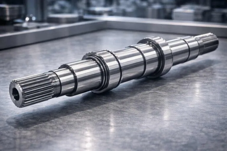



A dowel pin hole tolerance must be selected with the pin’s actual size limits, mounting method and locating pattern. Define the retained interface and the removable interface separately, then check whether all locating features can assemble together. A nominal diameter or an H7 callout alone is not a complete assembly specification. For example, Ganter describes an H7 hole paired with its DIN 6325 m6 pin as a transition fit, rather than a guaranteed interference fit. [1]
Application-guide disclosure: this is a hypothetical fixture-design study, not an MW+ customer project. Every numerical example below uses assumed limits solely to show a reproducible calculation. The examples establish neither acceptable insertion force nor validated repeatability, retention, service life or manufacturing capability.
The practical objective is an assembly review that distinguishes size, location and function. Our recommendations are intended to help a design owner organize that review; the released drawing and approved component data must supply the actual acceptance requirements.
All photographs are existing MW+ library illustrations. They do not depict the example fixture or verify a material, dowel fit or test result.
Contents
Separate the fixed pin seat from the removable interface
Start with an interface map. Which part retains the locator? Which part must lift off? Is the pin installed permanently, retained mechanically or intended for replacement? Carr Lane distinguishes plain and shoulder-type locating pins, press-fit mounting and renewable arrangements using liners and lockscrews. These alternatives have different installation and maintenance requirements. [4]
We recommend naming the surfaces independently on the drawing: base mounting seat, exposed locating land and mating locating hole. A stepped locator may have different mounting and locating diameters; never apply the mounting tolerance automatically to the land that contacts the workpiece. Request the current component drawing before completing either hole specification.
| Interface | Design question | Recommended evidence |
|---|---|---|
| Pin to fixture base | How is the locator retained and replaced? | Selected component drawing and approved retention method. |
| Locator to removable member | What assembly clearance and positional freedom are acceptable? | Mating limits and functional error budget. |
| Complete locating pattern | Can all features engage simultaneously? | Pattern analysis and assembly validation. |
| Seating and clamping | What establishes the final working condition? | Defined seating surfaces and assembly procedure. |
Assign responsibility for each decision. A purchased locator’s size range is an input to the fixture design, not permission to change the mating workpiece. If the base and removable member come from different suppliers, put both controlled interfaces in the same review package.
Dowel pin hole tolerance: calculate fit from actual limits
Use one sign convention throughout the review: C = H − P, where H is hole diameter and P is pin diameter. For independent size limits, the smallest diametral difference is Hmin − Pmax; the largest is Hmax − Pmin. These expressions are direct subtraction of the stated limits.
Under this size-only convention, positive C means diametral clearance and negative C means diametral interference. If the interval crosses zero, different permitted sizes can produce either outcome. Zero is an ideal line-to-line size result, not a practical assurance of easy assembly. Geometry and the actual mounting arrangement still need review.
Keep pin identity explicit. The cited Ganter product identifies an m6 fit dimension and cautions that its dimensions do not conform identically to ISO 8734. We therefore recommend checking the purchased part number and drawing instead of treating similar standard names as proof of interchangeability. [1]
Our calculation sheet should show units beside every input, identify whether a result is radial or diametral, and record the source revision. If an ISO fit designation is used, obtain the applicable limits for the actual nominal-size range from the governing reference; do not replace that lookup with the assumed numbers in this article.
Worked example: two interfaces with different requirements
Assumed model: a straight cylindrical pin has a diameter from 6.004 to 6.008 mm. A hypothetical base hole is 5.996 to 6.000 mm. A separate removable-member hole is 6.020 to 6.030 mm. These are deliberately specified limit dimensions, not an asserted H7/m6 fit or a recommended production design.
| Interface | Minimum H − P | Maximum H − P | Size-only finding |
|---|---|---|---|
| Base hole / pin | 5.996 − 6.008 = −0.012 mm | 6.000 − 6.004 = −0.004 mm | 4–12 µm diametral interference. |
| Removable hole / pin | 6.020 − 6.008 = +0.012 mm | 6.030 − 6.004 = +0.026 mm | 12–26 µm diametral clearance. |
The base calculation answers only whether the ideal size intervals overlap. It does not calculate the assembly force, stresses or retention capacity. For a real design, our recommendation is to obtain an approved interference-fit assessment using the actual materials, geometry, engagement, surface condition and installation requirements.
The removable hole has positive clearance throughout the assumed size range. With ideal circular sections and aligned axes, 0.012 mm diametral clearance corresponds to 0.006 mm radial freedom at that section; 0.026 mm corresponds to 0.013 mm. This division by two is geometric bookkeeping. It is not a measured positional repeatability or a complete three-dimensional assembly result.
Record both conclusions rather than writing “the dowel fits.” The retained interface and removable interface have different functions, and neither calculation establishes whether a second pin can engage. That requires the pattern check below.
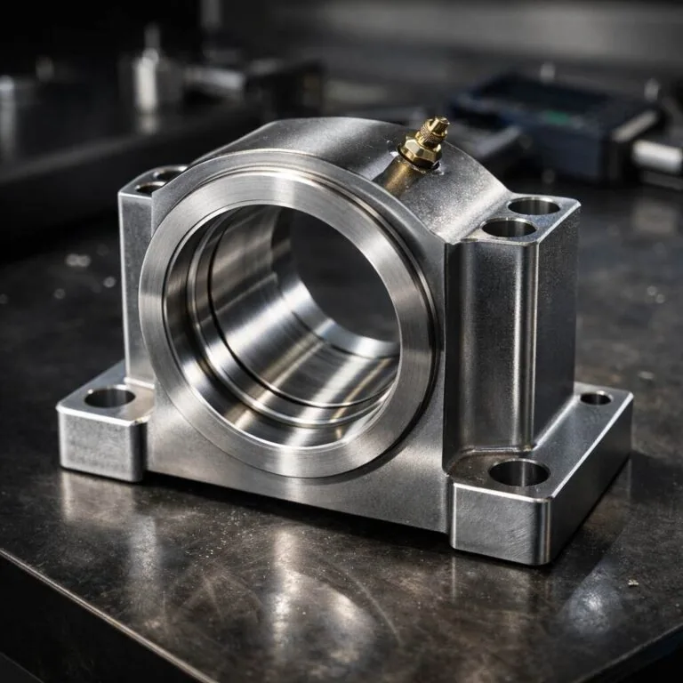
Check the whole two-pin pattern
Consider a second, explicitly simplified model: two parallel round pins engage two round holes in a rigid removable plate. Assume each interface has the minimum 0.012 mm diametral clearance from the previous example. Ignore tilt, form error, edge effects, friction, deformation and temperature. Only mismatch along the line between centers is considered.
Each center can shift by 0.006 mm relative to its mating center in this ideal model. The two interfaces together can therefore accommodate up to 0.012 mm of center-distance difference. This sum assumes the plate is free to translate into the most favorable position; it is not an additional allowance once another feature has fixed that position.
Now assume pin-center spacing is 100.000 ± 0.010 mm and hole-center spacing is 100.000 ± 0.020 mm. One permitted combination is 100.010 mm between pins and 99.980 mm between holes. Their spacing difference is 0.030 mm, exceeding the 0.012 mm accommodation by 0.018 mm. That combination cannot assemble in the stated rigid, aligned model.
| Hypothetical pattern item | Calculation | Meaning |
|---|---|---|
| Available shift at each minimum-clearance interface | 0.012 / 2 = 0.006 mm | Radial freedom in the ideal section. |
| Total center-distance accommodation | 0.006 + 0.006 = 0.012 mm | Only when free translation is available. |
| Extreme spacing difference | 100.010 − 99.980 = 0.030 mm | One permitted dimensional combination. |
| Unaccommodated difference | 0.030 − 0.012 = 0.018 mm | The simplified design does not guarantee assembly. |
Our recommended response is to revisit the locating scheme and error budget before reducing every tolerance. Ask which degree of freedom each feature must constrain and whether the design unintentionally duplicates that constraint. Keep other directions and the full engagement depth on the unresolved-check list.
Review a round-and-diamond alternative
Carr Lane describes a round pin as the primary two-axis locator and a diamond pin as the secondary one-axis locator. The relieved second locator avoids redundant location in the manufacturer’s arrangement. This provides a documented alternative to evaluating two fully round locators as though their pattern mismatch did not matter. [2] [3]
We recommend comparing the alternative with the actual workpiece datums, loading direction and required constraint. Use the selected manufacturer’s orientation drawing, contact geometry and mounting instructions. Carr Lane specifically warns that the diamond pin’s contact areas must be oriented correctly to perform their intended locating role. [4]
Changing the locator concept is not a substitute for verification. Request the actual relieved dimensions, remaining controlled direction, allowable mating geometry and wear criteria. Do not carry the preceding round-pin clearance calculation unchanged into a different locator shape. Record why the chosen scheme serves the functional requirement and which tests still need approval.
Complete the fixture drawing
ASME identifies Y14.5 as the language for communicating and interpreting GD&T requirements on drawings and digital product definitions. [5] For this fixture, our recommendation is to state the governing system and edition and then define the seating and locating relationships within that system. This article does not reproduce proprietary standard clauses or create a universal feature-control frame.
Put size limits, pattern location, orientation and relevant form requirements on the review agenda as distinct questions. KEYENCE describes true-position measurement relative to datums, which is a different check from subtracting hole and pin diameters. [6] For background terminology, see our guide to reading GD&T symbols; the present study stays focused on fixture assembly.
We suggest marking the controlled engagement length, entry geometry, pin projection and access for installation or replacement. Identify whether a hole is blind or through and ask the component supplier to confirm the appropriate mounting details. Do not invent a universal engagement multiple, chamfer, vent feature or press force from the nominal diameter alone.
Agree the machining and assembly route
For a machining enquiry, supply the base and removable-member drawings together with the locator drawing. Ask the supplier to propose the operation sequence and explain how the critical relationships will be preserved and measured. Keep approval of any process change tied to the released functional requirements.
Our recommendation is to name the finished feature rather than demand a generic “reamed hole” as a substitute for acceptance limits. The process proposal should resolve tool access, stock condition, finished-state dimensions and inspection. This guide does not establish which hole-making process a particular MW+ order will use or claim a universal tolerance for reaming.
Agree an installation plan before accepting the base-hole specification. Request how the part will be supported, how the insertion method is controlled and what evidence establishes the final projection and seating. Where replacement is expected, evaluate a renewable design rather than leaving removal to an undocumented maintenance operation. Carr Lane’s liner-and-lockscrew arrangement is one supplier-specific example of that approach. [4]
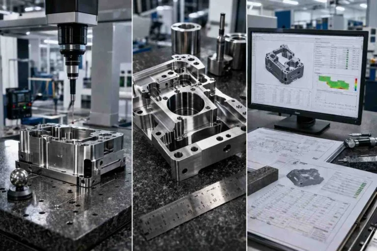
Build the inspection and validation record
KEYENCE distinguishes datum-related measurement from a simple size check and describes taking bore measurements at different depths when evaluating geometry. [6] We recommend separating the inspection record into component, installed-locator and assembled-fixture stages so that an acceptable loose pin does not silently become proof of the completed fixture.
At component stage, record the identified pin and relevant hole dimensions. At installed stage, review the locator’s projection, seating and relationship to the defined reference surfaces. At assembly stage, use an approved procedure that addresses loading, seating, clamping and unloading in the intended working configuration.
Before testing, agree what result would be acceptable and how it will be measured. A repeatability requirement needs a defined measured feature, loading sequence, number of trials and decision rule; the numbers must come from the application owner’s validation plan. A successful hand assembly of one chosen pair does not establish interchangeability across every allowed limit combination.
Keep measurement method, calibration status, environmental conditions and unresolved uncertainty visible in the report. These are our documentation recommendations, not claims that MW+ has inspected this hypothetical fixture. Ask the responsible engineer to approve the evidence needed before production release.
Release checklist
| Review item | Recommended release record | Open question to close |
|---|---|---|
| Locator identity | Part number, drawing revision and size limits | Does the supplied part match the approved input? |
| Retention interface | Base-hole limits and installation approval | What verifies retention without damage? |
| Removable interface | Mating limits and engagement geometry | What clearance and freedom does the application allow? |
| Pattern and datums | Approved geometric definition and assembly analysis | Can every controlled feature engage together? |
| Inspection | Component and installed-fixture records | Which method establishes each requirement? |
| Validation and maintenance | Functional procedure and replacement plan | Who approves the final assembly evidence? |
Frequently asked questions
Is an H7 hole always a press fit for a dowel pin?
No. The pin’s limits matter too. Ganter describes H7 paired with its cited DIN 6325 m6 product as a transition fit. Check the exact pairing and size range before choosing a retention method. [1]
Can a hole with positive clearance still fail to assemble?
Yes in a multi-feature pattern. The hypothetical two-pin example has clearance at each individual interface but an allowed spacing combination that exceeds the available center-distance accommodation. That conclusion belongs only to the stated model; a real design needs its full geometry checked.
Why use a diamond locating pin?
Its relieved locating geometry can avoid redundant location when paired correctly with a primary round locator. Select and orient it using the component manufacturer’s instructions rather than assuming that every relieved pin works in any orientation. [3] [4]
Does this example specify a recommended dowel pin press fit?
No. The assumed limits illustrate interval arithmetic. They do not establish acceptable force, stress, retention or service behavior. The actual design authority must approve the fit using the selected component and application evidence.
Does a CMM report alone prove fixture repeatability?
Our recommendation is to distinguish dimensional conformity from functional validation. A report should identify what was measured and in which state. Require a separate approved assembly procedure and repeatability evaluation when that performance is part of the specification.
Prepare a manufacturing enquiry
When discussing precision components with locating features, include both mating drawings, the purchased locator data and the acceptance plan. Clearly mark which dimensions are already released and which remain under engineering review.
For CNC manufacture of the fixture plate and locating holes, request a scope that covers the critical relationships, finished-state measurements and any approved installation work. Confirm proposed responsibilities before order release.
Use the MetalWorksPlus company overview for company context, then keep the enquiry specific to the fixture. The useful outcome is an agreed drawing and evidence package, with retention, assembly and validation questions resolved by their designated owners.