A part does not become a multi-axis job because it looks complicated on screen. It becomes one when a straight tool axis cannot reach a surface, or reaches it only at a cutting speed that ruins the finish, or reaches it only by putting the part back in a fixture again. Those are three failures with three different answers, and separating them turns a complex part multi axis machining decision into engineering judgement.
Key takeaways
- Reach, tool orientation and setup count are different problems. Indexed 3+2 solves the first and third; only simultaneous motion solves the second.
- A ball-nose cutter held normal to a surface cuts at zero speed at its centre. The worked example below shows a 25° tilt taking effective cutting speed from about 81 to about 163 m/min on a 6 mm ball nose at 0.2 mm depth, 12,000 rev/min.
- Every refixture spends tolerance. Four setups at an assumed 0.008 mm relocation repeatability consume roughly 70 per cent of a 0.02 mm true-position budget statistically, and overrun it in the worst case.
- Machine capability is a published test, not a claim: ISO 230-2:2014 for linear positioning, ISO 230-7:2015 for axes of rotation, ISO 10791-6:2014 for interpolation.
- General tolerances have moved. ISO 2768-2:1989 is withdrawn, replaced by ISO 22081:2021; a second edition of ISO 2768 is in publication to replace ISO 2768-1:1989. State which governs.
- More axes are often the wrong answer — four counter-cases are set out below.
On this page
- What actually makes a part complex?
- Axis configurations and what each reaches
- Why does three-axis leave a poor finish on a sculpted surface?
- Setup count is an error budget
- Which geometry actually forces a rotary axis
- Which standards govern multi-axis accuracy?
- Does material change the axis-count decision?
- What the drawing must say
- When multi-axis is the wrong call
- Frequently asked questions
What actually makes a part complex?
Complexity is not feature count. It is the degree to which a part’s features disagree about how it should be held and which way the tool should point. Three conditions do the work.
Accessibility — the tool cannot reach the surface
A three-axis centre moves along X, Y and Z with the tool axis fixed parallel to Z. Any surface whose outward normal points away from +Z beyond the tool’s clearance is unreachable, or reachable only with a tool too long to stay rigid: undercuts, re-entrant faces, compound-angle ports, cavities with draft in two directions.
Orientation — the tool reaches it, but not usefully
This is missed most often at quote stage, because CAM generates a toolpath regardless. A sculpted surface can be cut in three axes with a ball nose, but only with the axis vertical; where the surface lies near horizontal the contact point migrates to the ball centre, which rotates about itself and has no surface speed. The result is rubbing, not cutting.
Datum integrity — the features must agree with each other
When a callout relates a feature on one face to a datum on another, every unclamping re-establishes that relationship through the fixture rather than the machine, and the transfer’s repeatability is spent out of the tolerance the designer allocated.
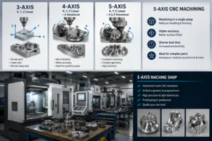
Axis configurations and what each reaches
“Five-axis” is used loosely, hiding a real distinction between machines that orient the tool and then cut, and machines that orient it while cutting.
| Configuration | Tool axis while cutting | Suited to | Limitation |
|---|---|---|---|
| 3-axis | Fixed, parallel to Z | Prismatic parts, 2.5D pockets, drilling normal to one face | One face per setup; no undercut access |
| 3+1 indexed | Fixed per cut, re-indexed between cuts | Features around a cylinder, ports on a bolt circle | Rotary axis is a positioner, not a contouring axis |
| 3+2 indexed | Fixed at an arbitrary compound angle per cut | Compound-angle holes, multi-face parts in one clamping | Cannot follow a changing surface normal within a pass |
| 5-axis simultaneous | Continuously reoriented while cutting | Blades, impellers, manifolds, deep cavities needing short tools | Highest programming and verification effort |
The commercial point: 3+2 solves accessibility and datum integrity without solving orientation; simultaneous five-axis solves all three. Many parts called five-axis in an RFQ need only 3+2, which is cheaper to programme and easier to verify. Our multi-axis machining page lists which configurations run in which envelope, and 5-axis vs 3-axis: a decision guide works the choice from the part’s side.
Why does three-axis leave a poor finish on a sculpted surface?
Because cutting speed at the contact point is not the speed on the tool’s data sheet. On a ball nose it depends on engagement depth and on tilt relative to the surface, and held vertically on a near-horizontal face the contact point sits at the ball centre, where effective diameter approaches zero.
Worked example: effective diameter and surface speed
A 6 mm ball-nose end mill (radius R = 3 mm) at 0.2 mm axial depth, 12,000 rev/min. This is geometry, not a performance claim.
Case 1 — axis normal to the surface. The engaged arc runs from the tool centre out to:
Deff = 2 √(ap (D − ap)) = 2 √(0.2 × 5.8) = 2 × 1.077 = 2.15 mm
vc = π Deff n / 1000 = π × 2.15 × 12000 / 1000 = 81 m/min
At the tool centre, effective diameter and cutting speed are both zero: that part of the flute burnishes rather than cuts, work-hardening the surface ahead of it and abrading the edge.
Case 2 — axis tilted 25° from the normal. The half-angle of engagement is
θ = arccos((R − ap) / R) = arccos(2.8 / 3) = 21.0°
So the engaged band runs from 4.0° to 46.0°, and the largest engaged diameter is
Deff = D sin(46.0°) = 6 × 0.720 = 4.32 mm, giving vc = 163 m/min
Two results fall out. The tilt roughly doubles usable cutting speed at this depth, so the same finish is reached with a larger stepover and fewer passes. And the tilt must exceed arccos((R − ap)/R) — about 21° here — before the zero-speed centre leaves the cut at all; a 10° tilt does not partly fix this, it does not fix it. That explains a familiar quoting pattern: a surface a three-axis machine can reach still returns a long cycle time, because the only route to an acceptable finish from a zero-speed contact point is very light passes at a very small stepover, repeated many times.
Setup count is an error budget
Each extra setup adds fixturing, clamping, datum probing and a first-article check. Those costs are visible; the hidden one is the tolerance it consumes.
Worked example: what four setups cost a positional callout
Assume — as inputs to the arithmetic, not measured figures — 0.008 mm relocation repeatability per refixture, against a 0.02 mm true-position requirement relating a bore on one face to a datum on another face.
| Route | Relocations | Worst case (arithmetic) | Statistical (root-sum-square) | Share of 0.02 mm budget |
|---|---|---|---|---|
| 3-axis, four setups | 3 | 3 × 0.008 = 0.024 mm | 0.008 √3 = 0.0139 mm | about 70 per cent |
| 3+2, two setups | 1 | 0.008 mm | 0.008 mm | about 40 per cent |
| 5-axis, one setup | 0 (rotary positioning assumed 0.004 mm) | 0.004 mm | 0.004 mm | about 20 per cent |
The four-setup route fails the worst case outright — 0.024 mm against a 0.02 mm budget — and even statistically leaves only about 30 per cent for machine positioning, tool deflection, thermal growth and measurement uncertainty combined. One setup leaves about 80 per cent. The claim is not that five-axis is inherently more accurate; it is that when callouts cross faces, setup count spends a resource the designer already allocated, and which case you have is readable from the drawing before anyone quotes. The companion article on what ±0.005 mm means in production covers verification once a tight band is committed.
Which geometry actually forces a rotary axis
Specifying more than the minimum configuration is avoidable cost, so the table gives the minimum that resolves each feature and the design change that removes the need.
| Feature | Why a fixed tool axis struggles | Minimum configuration | Design change that avoids it |
|---|---|---|---|
| Hole on a compound angle | Tool axis cannot align to the hole axis | 3+2 indexed | Align the hole to an existing face normal |
| Sculpted surface, changing normal | Contact wanders into the zero-speed ball centre | 5-axis simultaneous | Flatten the near-horizontal region |
| Wall thinner than about 1 mm over a long span | Part deflects away from the tool | Axis count does not solve it | Thicken the wall, or add a sacrificial rib removed last |
| Tight callouts across four or more faces | Each refixture re-establishes the datum relationship | 3+2 or 5-axis, for setup reduction | Move the tight callouts onto one face |
| Small corner radius in a deep pocket | Small cutter cannot reach depth; large cutter cannot make the corner | Rest machining with a second, shorter tool | Increase the corner radius — the highest-leverage change available |
The right-hand column holds the largest savings and is skipped most often: raising a pocket’s corner radius, or flattening a near-horizontal cosmetic region, removes cost instead of moving it to a more capable machine. Deep cavities behave the same way — beyond about four times the tool diameter, tilting the head to shorten the reach beats extending the tool. Where a part becomes genuinely prismatic after those changes, ordinary CNC milling services produce it more cheaply than any five-axis route.
Which standards govern multi-axis accuracy?
A capability claim means something only if it names the test behind it. Machine geometry under no-load conditions is covered separately by ISO 230-1:2012, and thermal behaviour by ISO 230-3:2020.
| Standard | What it defines | What to ask for |
|---|---|---|
| ISO 230-2:2014 | Positioning accuracy and repeatability of NC axes | Bidirectional accuracy and repeatability per linear axis |
| ISO 230-7:2015 | Geometric accuracy of axes of rotation | Error motions of the rotary and tilting axes |
| ISO 10791-6:2014 | Accuracy of speeds and interpolations on machining centres with three linear plus one or two rotary axes | Interpolation test results — the closest published proxy for simultaneous behaviour |
| ISO 10791-7:2020 | Accuracy of finished test pieces | A machined and measured artefact, not only an electronic test |
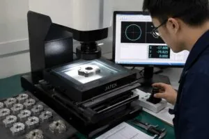
| ISO 10360-2:2009 | Acceptance and reverification of CMMs measuring linear dimensions | The CMM’s maximum permissible error, so report uncertainty is known |
The distinction that matters is between the ISO 230 series, which tests the machine, and ISO 10791-7, which tests a machined artefact. A machine can pass axis-by-axis tests and still cut an out-of-tolerance test piece, because five-axis error sources — rotary offsets, pivot-point calibration, controller kinematic error — appear only when axes move together. Asking for a finished test piece closes that gap, which is why our CNC machining quality control ties verification to the setup rather than to a general machine specification.
Does material change the axis-count decision?
It does, in two directions. Titanium alloys and nickel superalloys conduct heat poorly, so heat that should leave with the chip stays in the cutting zone and the tool must hold steady engagement — dwell and re-entry destroy tools here, which is what continuous five-axis paths avoid. Aluminium pulls the other way: it cuts so freely that cycle time is dominated by non-cutting motion, above all setup, so where callouts do not cross faces a three-axis fixture holding several parts is usually cheapest.
| Material | Linear expansion (µm/m per K, near room temperature) | Heat behaviour | Bias in the decision |
|---|---|---|---|
| Aluminium 6061-T6 | about 23.6 | High conductivity; heat leaves with the chip | Fewer setups for time, but watch growth on long cycles |
| Stainless 304 | about 17.3 | Moderate; work hardens readily | Toward continuous engagement |
| Alloy steel 4140 | about 12.3 | Moderate | Neutral; setup rigidity matters more |
| Ti-6Al-4V | about 8.6 | Low; heat stays in the cutting zone | Strongly toward simultaneous five-axis and short tools |
MW+ runs 70+ materials across 60+ machining centres. Material is usually settled before the axis question is raised, but it is worth re-opening once: a substitution neutral for function can move a part between those two columns.
What the drawing must say
Most disagreement about axis count is really disagreement about what the drawing requires:
Name the general tolerance regime and its edition
“General tolerances per ISO 2768-m” is no longer unambiguous. ISO 2768-2:1989, which covered general geometrical tolerances, is withdrawn and replaced by ISO 22081:2021, and a second edition of ISO 2768 is in publication to replace ISO 2768-1:1989. Drawings in circulation use all three conventions, so name the edition or accept the supplier’s choice of it.
Separate the callouts that must hold from the inherited ones
A tolerance carried over from a template looks identical, to a quoting engineer, to one that was calculated. Mark the features that control fit and let the rest fall to the general tolerance. MW+ works to ±0.01 mm against ISO 2768-m generally and down to ±0.001 mm where a feature needs it, but the two cost very different amounts to verify. Surface requirements need their parameter and edition named too: ISO 21920-2:2021 (superseding ISO 4287) defines the parameters, ISO 21920-3:2021 (superseding ISO 4288) the sampling and filtering, and ISO 21920-1:2021 (superseding ISO 1302) the drawing indication. On a sculpted surface, finish forces simultaneous five-axis more often than reach does.
Also give a datum scheme reflecting how the part is used rather than how it was drawn, and state the expected quantity. MW+ returns quotations within 24 hours on STEP, IGES, DXF, DWG, SolidWorks and PDF; you can request a CNC machining quote with the drawing attached. For geometry still being proven, CNC prototyping in 3–5 business days, or 48-hour express, settles the axis question faster than more analysis.
When multi-axis is the wrong call
The argument above is one-sided by design. Four situations where adding axes makes a part slower, worse or more expensive:
The part is prismatic and the volume is high
If all tight callouts sit on one face and the order runs to thousands, a dedicated fixture holding six or eight parts on a three-axis machine beats a five-axis cell per part. The five-axis advantage is setup reduction, and setup amortises away at volume.
The limiting error is part deflection, not machine capability
Thin walls, long unsupported spans and low-modulus materials deflect under cutting force. That error belongs to workholding and cutting strategy, not axis count: moving the part to a five-axis machine adds cost and leaves the wall exactly as thin. The fix is a fixture that supports it, lighter radial engagement, or a rib removed in the final operation.
Programming and proving exceed the machining time saved
Simultaneous paths need collision simulation against real machine kinematics, not a generic model, with current pivot-point calibration. On a one-off with a short cycle that can outweigh the whole three-axis alternative, so prototypes are often better made in three axes and two setups, with five-axis reserved for production once geometry is frozen.
The rotary axes add error the part cannot absorb
Rotary axes have error motions of their own, covered by ISO 230-7:2015, and the kinematic model introduces offsets needing repeated calibration. On features tighter than the rotary axes hold, a single well-fixtured three-axis operation with a probed datum is more accurate even though it needs a second setup — here the setup-count argument reverses. Axis count solves reach, orientation and datum problems; where none of the three binds, it solves nothing and costs money.
Frequently asked questions
My supplier quoted five-axis for what I think is a three-axis job. How do I challenge it?
Ask which of the three constraints drives it. If reach, which feature is inaccessible, and would a 3+2 index clear it? If orientation, which surface and what finish parameter? If datums, which callout crosses faces? A supplier who cannot name the feature is quoting an impression of the model, and the conversation belongs in design review, not price negotiation.
Is 3+2 indexed machining as accurate as simultaneous five-axis?
For a feature machined entirely within one indexed orientation, 3+2 is usually more accurate, because the rotary axes are clamped during the cut and contribute no dynamic error. Simultaneous motion wins only where the surface itself demands a moving tool axis; treating it as a superset adds error sources without adding capability.
Does a single setup remove tolerance stack-up?
No. It removes the relocation contribution, usually the largest single term, but substitutes rotary positioning and kinematic model error — 0.004 mm against 0.0139 mm in the worked example above. That is why one setup helps, though on very tight features the substitution can dominate.
Which single design change most reduces the cost of a complex part?
Increasing internal corner radii in pockets. The radius governs minimum tool diameter, which governs the depth reachable rigidly, the feed rate and the number of rest-machining passes. It is usually there for stress reasons a larger radius serves as well, it is free to change in CAD, and impossible to change later.
Should I specify the machine configuration in my RFQ?
Generally no, and doing so can cost you money. Specify geometry, the tolerances that matter, the datum scheme and the surface requirement, then let the supplier route the part; mandating five-axis removes their ability to find a cheaper equivalent. Our guide to 3-axis versus 5-axis cost and accuracy covers where the crossover sits.
How does volume change the answer?
Setup cost is fixed per batch and amortises with quantity; cycle time is paid per part. Multi-axis routes mainly reduce setup, so their advantage is largest at low and medium volume. At high volume a dedicated fixture on simpler machines often overtakes them. The companion article on how geometry shapes production costs develops the cost side.
What evidence proves a supplier’s multi-axis capability is real?
Three documents: machine test results to ISO 230-2:2014 and ISO 230-7:2015; a machined and measured test piece per ISO 10791-7:2020; and the CMM’s maximum permissible error under ISO 10360-2:2009, so report uncertainty is known rather than assumed. Every MW+ order ships with a certificate of conformance, a CMM inspection report and material certificates, with first article inspection to AS9102 or PPAP Level 3 quoted per programme.
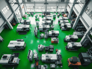
MW+ has machined to that decision sequence since 2015, from a 15,000 m² facility in Shenzhen with 60+ machining centres and 120+ engineering and quality professionals, holding ISO 9001:2015, AS9100D, ISO 13485, IATF 16949 (which replaced ISO/TS 16949) and NADCAP approvals. Where a part turns out to be prismatic after all, CNC precision parts made in fewer axes is the better answer, and saying so is part of the job.